Summary of Pinewood Derby Car Scale With Center-of-Gravity (CG) Calculation
This article details a DIY Arduino-based project to build a scale for Pinewood Derby cars that measures axle weight and calculates the Center of Gravity (CG). The device uses two load cell sensors and an LCD display to help builders optimize car performance by positioning mass correctly, typically ¾" forward of the rear axle.
Parts used in the Pinewood Derby Car Scale With Center-of-Gravity Calculation:
- Arduino UNO Microcontroller Board
- HX711 Load Cell Sensor with ADC Module (Qty=2)
- Miniature toggle switch SPDT with center off position
- Miniature toggle switch SPST
- 5.5mm Power Receptacle Panel Mount
- 9VDC Power Supply Adapter
- Miniature pushbutton switch SPST N.O. (Qty=3)
- 20 X 4 LCD Display with I2C Backpack
- Prototyping circuit board
- Hardwood Poplar or Ash Board
- Pine wood blocks
- ¼ Spacers/standoffs
- Acrylic or Plexiglas sheet
- M4-0.7 X 20 mm Flat Head Phillips Screws
- #4 x 3/8 Pan Head Phillips Screws
- Assorted Wood screws
- Fine Tip Soldering Iron
- Rosin Core 60/40 solder
- Calibration weight
A key factor when building a pinewood derby car is its weight. The Boy Scouts of America and other organizations specify a weight of no more than 5 ounces. To improve performance many builders will add as much weight (mass) as possible up to that maximum allowable weight limit. What is often overlooked is the car’s center of gravity (CG) (AKA Center-of-Mass). Too far back and the car’s front wheels risk the possibility of jumping the track. Too far forward and you lose out on a few extra inches of acceleration during the downhill part of the track. Many pinewood car building experts agree that the ideal CG location is about ¾” just forward of the rear axle (assumes a standard pinewood derby car wheel base of 4 3/8”). There already are many gadgets on the market that help you determine your car’s CG. But since we need a scale to weigh the car anyway I thought that if the scale can also determine the car’s CG at the same time it would make the task of adding weights to the car a bit easier. I realized that if I can simultaneously and separately measure the weight at both the front and rear axles, I can easily calculate the CG. Having played around with the HX711 load cell sensors in the past I knew this would be a great Arduino based project.
This project uses two inexpensive HX711 load cell sensors to measure the front and rear axle weight, a 4 row, 20-character Liquid Crystal Display (LCD) to display the weights and CG, some switches and an Arduino UNO microcontroller to do all the computing.
Supplies
The electrical parts required for this project are listed below.
- Qty=1 – Arduino UNO Microcontroller Board
- Qty=2 – 1 KG Scale Load cell Sensor, w/ HX711 ADC Module
- Qty=1 – Miniature toggle switch, SPDT with center off position
- Qty=1 – Miniature toggle switch, SPST
- Qty=1 – 5.5mm Power Receptacle, Panel Mount
- Qty=1 – Power Supply Adapter, 9VDC, 400ma (minimum) with 5.5mm Power Plug
- Qty=3 – Miniature pushbutton switch, SPST N.O.
- Qty=1 – 20 X 4 LCD Display w/ I2C Backpack, 5 Volt
- Qty=1 – Prototyping circuit board for mounting the HX711 ADC modules (Optional)
The wooden enclosure (case) shown in this project is built from the following materials:
- ¼” x 2.5” x 48” Hardwood Poplar or Ash Board for the sides, Home Depot #:719931245984
- Qty=2 – Pine wood blocks 0.75” x 1.0” x 3.625” in which to mount the load cells
- Qty=4 – ¼” Spacers/standoffs for mounting load cells to pine wood blocks
- Acrylic or Plexiglas or Polycarbonate sheet or tempered hardboard for the weighing platforms
- Qty=4 – Spacers, TBD length for mounting weighing platforms to load cells
- Qty=4 – M4-0.7 X 20 mm Flat Head Phillips Screws for mounting weighing platforms to load cells, Home Depot #: 887480117585
- Qty=4 – #4 x 3/8” Pan Head Phillips Screws for mounting front panel
- Assorted Wood screws for attaching load cells to support blocks and the base to the enclosure
Tools & Materials
- Computer – Used for programming the Arduino UNO microcontroller
- Software: Arduino Integrated Development Environment (IDE) – Free download from https://www.arduino.cc
- Fine Tip Soldering Iron
- Rosin Core 60/40 solder
- Standard hand tools, wire cutter, wire strippers, needle nose pliers
- Wood working tools
- Wood glue
- Calibration weight whose exact weight is known (Suggest between 1 & 5 ounces).
Step 1: Building the Enclosure
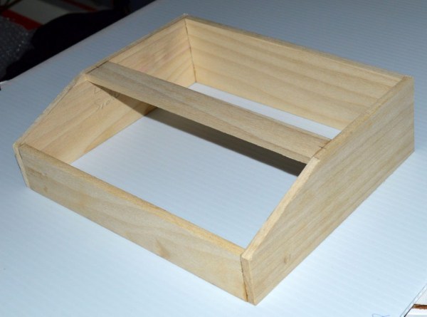
There are many options when it comes to the enclosure for housing the project including the purchase of a plastic or metal project box. A key requirement for the enclosure is that it have a solid, sturdy base on which the load cells are mounted so as to avoid any flexing or movement when weight is applied. I decided to build my own from wood and have included the build plans in the accompanying photos.
Step 2: Building the Control Panel
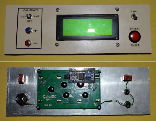
I chose to build the control panel using a standard piece of 0.019” thick aluminum sheet metal cut to 3” x 9”. An electric drill was used to drill the holes for the switches and screws. A manual hand-held punch-and-die type sheet metal nibbler tool was used to cut the rectangular hole for the LCD display. The panel was then spray painted and allowed to dry. A label maker was used to create the switch legends and a fine point Sharpie™ permanent marker was used to draw the rectangle around the calibration switches.
Step 3: Fabricating the Weighing Platforms
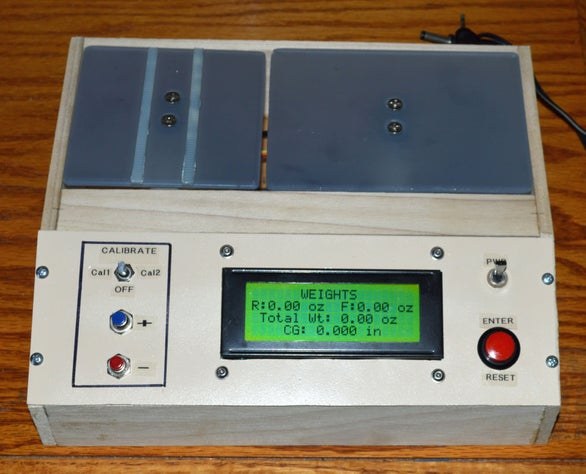
I designed the scale to weigh cars of varying wheel base with the intent to always have the rear axle positioned at the same location on its weighing platform. Hence, the weighing platform for the front axle was made longer to accommodate different wheel base lengths. The weighing platforms can be made from wood, metal or plastic as long as it is thick enough to be rigid. Spacers are used to raise the platform so it doesn’t touch the load cell and to attain an appropriate height so that the surface is flush with or slightly higher than the top of the enclosure. I happened to have a few pieces of frosted plastic lying around so I used it as my platform material. Since the plastic was semi-transparent it made it easy to locate the drill holes for attaching the platform to its load cell. M4-0.7 x 20mm metric flat head Philips screws were used to attach the platform to the load cell. Care should be taken so that the weighing platform does not touch or rub against any enclosure surface. You may have to do some fitment checks and trim the edges to ensure there is adequate clearance. Additionally, I glued two plastic strips on the rear axle weighing platform so that when the car is placed on the scale, it doesn’t roll away.
Step 4: Wiring
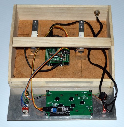
Prefabricated Arduino breadboard jumper ribbon cable was used to connect the front panel switches and LCD display to the Arduino. The HX711 ADC modules were mounted on a prototyping circuit board which was then used to piggyback onto the Arduino to provide the power, ground, clock (sck) and data (dt) connections. A 2 wire cable with a 5.5mm power plug was used for the power wiring. See attached schematic diagram.
Step 5: Installing the Arduino Software
It is assumed you are already familiar with using the Arduino Integrated Development Environment (IDE) for uploading the code to your Arduino board. If not, the Arduino and Instructables website have plenty of tutorials to help you get started.
The Arduino source code is well commented making it easy to tell what each section of the code is doing. Hence, it will not be discussed in detail here.
Additional Libraries Required
The code uses the following libraries that must also be resident on your PC. Refer to the Arduino website or YouTube for instructions on how to install these libraries.
- Wire (Installed by default)
- HX711_ADC
- LiquidCrystal_I2C
- EEPROM
Software Features
Aside from displaying the weights and CG, the software has the following features:
- Ability to adjust the wheel base (axle separation) used in the CG calculation
- Ability to adjust the value of the calibration weight used for calibrating the scales.
- On-screen step-by-step instructions when calibrating the scales.
- Save calibration values to the Arduino’s EEPROM for storage and future use.
- Ability to reset the scales (i.e. perform a Tare function to zero the scale).
Step 6: Operation – Setting the Wheel Base
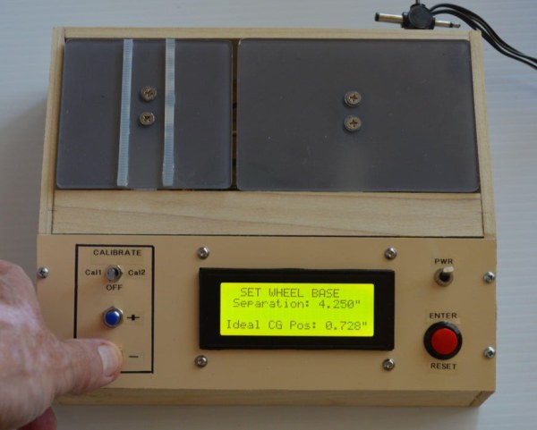
In order to calculate the CG in inches just forward of the rear axle the software must know the car’s wheel base (Axle Separation). The default setting is 4.375 inches which is the default wheel base of most pinewood derby car kits. However, the wheel base setting can be adjusted between 2.0 and 7.0 inches in 1/8 inch increments. As the wheel base is adjusted the optimum or ideal CG position is calculated and displayed as a reference for comparison to the actual measured CG. To increase or decrease the wheel base press and hold the + or – button. The display will show the current set value.
Step 7: Operation – Setting the Calibration Weight Value
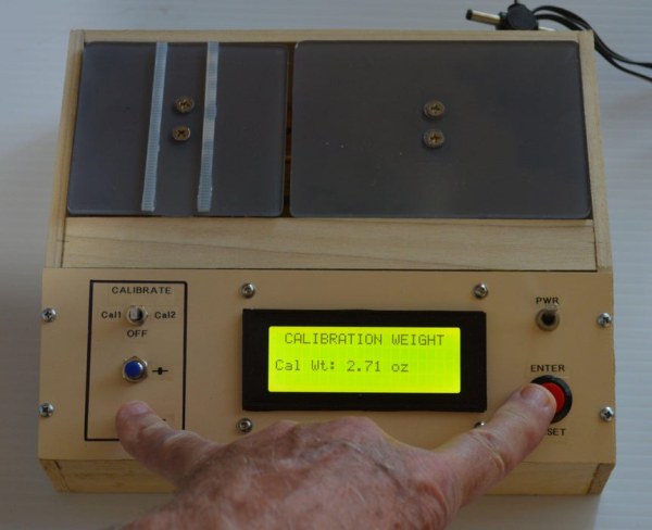
In order to calibrate the scales (load cells) the software must know the weight (mass) of the calibration weight used to calibrate them. If you know your calibration weight value before you upload the software to the Arduino, you can set it in the Setup section of the code (e.g. calMass = 2.72) as the default value. Otherwise you can set it using the following procedure: Simultaneously press and hold the ENTER and the + or – buttons. The display will show the value increasing or decreasing in 0.01 ounce increments. Release the buttons when the desired value is displayed. The software will store this value in EEPROM for future use.
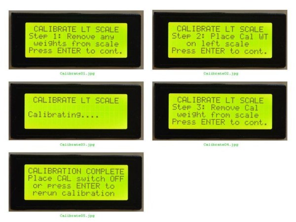
Step 8: Operation – Calibrating the Scales
Calibrating the HX711 load cells is in most cases a onetime event when the unit is powered up for the first time. If you have already determined the calibration values for your load cells using a separate software utility those values can be set in the Setup section of the code (e.g. calFactor1 = 25228.3 & calFactor2 = 23571.7 ) as the default values before you upload the software to the Arduino. In this project the capability to calibrate the two scales is built in and the values are saved in EEPROM so that they are permanently remembered. Before we can calibrate the scales we must have a calibration weight whose exact weight is known down to 0.01 ounces. This can be any small object on hand (i.e. a lead weight, large metal bolt, etc.) whose weight is known. A separate commercial digital scale can be used to weigh the object to be used. For best results it is recommended the calibration weight be between 1 and 5 ounces.
To calibrate the scales perform the following:
- Set the weight of the calibration weight to be used per the directions provided in the previous section.
- Place the calibration switch to the Cal1 position (Rear axle).
- Follow the on-screen instructions for calibrating the left (Rear axle) scale.
- Place the calibration switch to the Cal2 position (Front axle).
- Follow the on-screen instructions for calibrating the right (Front axle) scale
Step 9: Operation – Weighing Your Pinewood Derby Car

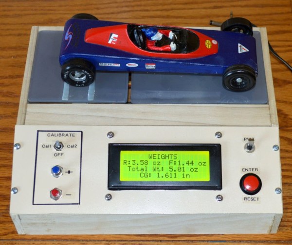
Once the scales have been calibrated and the wheel base has been set you are ready to weigh your car. To weigh your car place it on the scale so that the rear axle is on the left platform and the front axle is on the right platform (Refer to Figure 6). Allow the scale to stabilize before recording the readings. The CG value displayed is the distance in inches just forward of the rear axle. As you add weights during your car’s weight adjustment you can immediately see the effect on the CG and adjust the weight position accordingly to optimize the CG.
From what I’ve gleaned from other car builders the optimum CG position for a car with a 4 3/8” wheel base is somewhere between 5/8” and 7/8” just forward of the rear axle which translates into a 17.2% +/- 2.8% of the total wheel base. Said in a different way, the optimum CG is attained when 17.2% of the car’s total weight is on the front axle and the remainder (82.8%) of the weight is on the rear axle. That distance is easily calculated using the following equation:
Optimum (Ideal) CG position: Dcg = 0.172 * Wheel Base
If the weight on each axle is known, the actual CG is easily calculated using the following equation:
Actual CG position: Dcg = Front Axle Weight/Total Weight * Wheel Base
CAUTION: The load cells used in this project are rated for a maximum weight of 1 KG (35.27 ounces). Placing objects heavier than this may damage the load cell. HX711 load cells rated at 2, 3, 5, 10 and 20 KG are available if you plan on weighing heavier objects.
Source: Pinewood Derby Car Scale With Center-of-Gravity (CG) Calculation
- What is the ideal CG location for a standard pinewood derby car?
The ideal CG location is about ¾ inch just forward of the rear axle. - How can you determine the car's center of gravity using this project?
You measure the weight at both front and rear axles separately to calculate the CG. - Can the wheel base setting be adjusted on the scale?
Yes, the wheel base setting can be adjusted between 2.0 and 7.0 inches in 1/8 inch increments. - What is the recommended weight range for the calibration object?
It is recommended that the calibration weight be between 1 and 5 ounces. - Does the software save calibration values for future use?
Yes, the software saves calibration values to the Arduino's EEPROM for storage. - What happens if the center of gravity is too far back?
If the CG is too far back, the car's front wheels risk jumping the track. - How do you place the car on the scale for weighing?
Place the car so the rear axle is on the left platform and the front axle is on the right platform. - What is the maximum weight rating for the load cells used?
The load cells are rated for a maximum weight of 1 KG or 35.27 ounces.