¿What questions need to be resolved?
-
¿How to recognize the origin of the table? — The table is the piece of the machine where you place your board, and is critical for the pick and place operation. I’ve thinking in a limit switch system.
-
Will be the use of the “tglue layer” of the Eagle program, the correct choice for getting the position of the SMT components? — As I’ve been investigating, it’s going to work.
¿What tasks need to be completed?
-
The last revision to the motors drivers’ board
-
The control program
What has worked? what hasn’t?
-
What really worked, was the use of a commercial syringe for the pick up tool, of course that was not so straightforward, we had to test several syringe models and wire springs also. Finally with the aid of a rubber vacuum cup worked as expected.
-
Not yet, but it’s going to work, the exact alignment of the pick up tool and the component’s position
What will happen? When?
The alignment of the pick up tool and the component’s position is a mechanical problem, is due that we are using leadscrews of the same diameter but different steps by inch, unfortunatelly that was sourced locally.
I expect to finish the program before the final project presentations.
Documenting the progress
As mentioned in the assigment “Applications and Implications”, the parts to be made for the Pick and Place (PnP) machine are:
- The cabinet and tool support for the pick and place tool
- The dispenser
- The pick and place tool
- The electronics controller
- The software
The mechanical specifications for the cabinet are:
| X(mm) | Y(mm) | Z(mm) | |
|---|---|---|---|
| Cabinet | 375 | 175 | 250 |
| Base | 440 | 335 | —— |
| Bed | 305 | 120 | 70 |
Other important requirements are:
- Low cost materials
- Easy assembly and maintenance
- Multipurpose (milling, solder dispenser, heating gun)
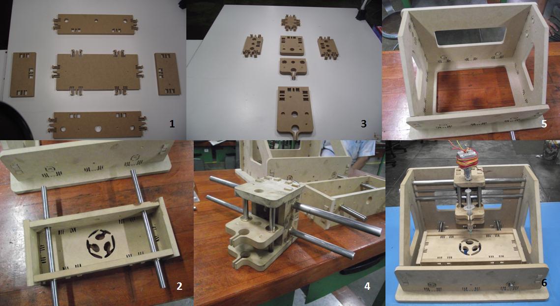
For the cabinet implementation we are going to make first a prototype in MDF and after the final design, test and evaluation we will make the machine in HDPE.
The cabinet components were computer controlled machined in the shopbot, then we proceeded with assembly, as the figure shows.
One of the important tools raised for this project is the dispenser. The components are placed on the dispenser and will be taken from there to be transferred to the card. The reason for using a dispenser is because it faciltates the transport of the components to the board. There will be a dispenser for each card model.
I manufactured the components’ dispenser in assignments 5 and 7, I made two models, one casted with Hidro-Stone and the other printed in ABS.
The pick and place tool was manufactured with a hypodermic syringe, a wire spring and a vacuum pick up tip. We had problems with suction of components, we fixed this applying a silicone sealant between the needle and the suction tip, and a lubricant in the plunger of the syringe. I also tried with other types of syringe like the showed in the figure; it has a plastic needle, but it hasn’t enough suction because the diameter of the plastic tip was big respect the diameter of the rubber suction tip used with the metal needle. I’ve seen this plastic needle been used in systems with a vacuum pump for improving suction of surface mount devices.
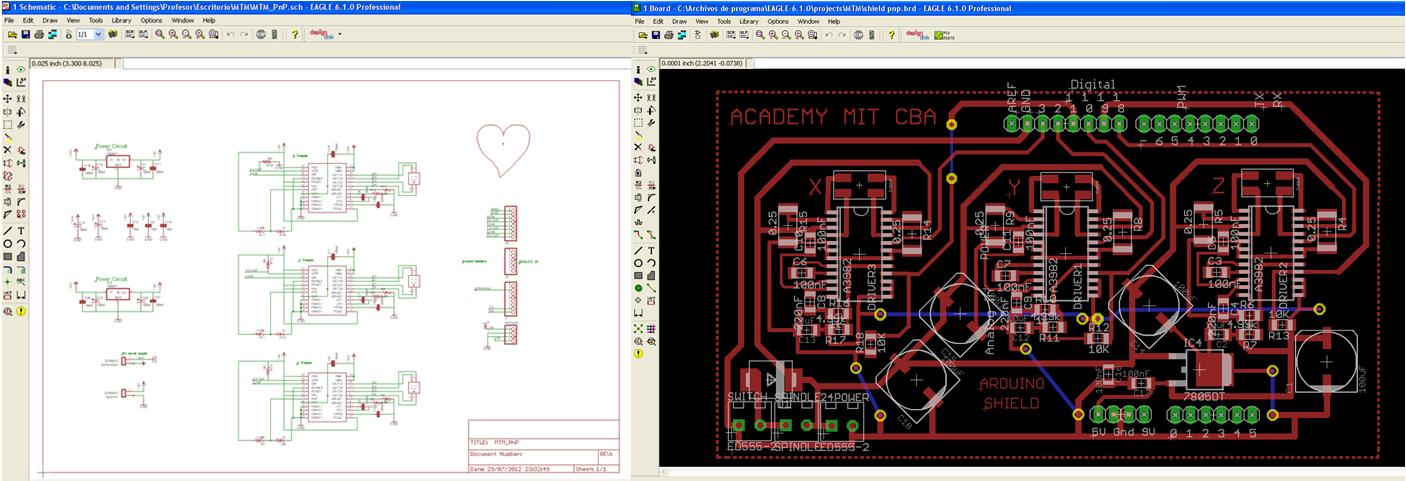
The electronic controller design was based in the Allegro A3982 Stepper motor controller with translator, this means that simply inputting one pulse on the STEP input drives the motor one step. There are no phase sequence tables, high frequency control lines, or complex interfaces to program as with other circuits, this is the same chip used by the MTM Snap lock machine. Some of the advantages here:
- Only one chip to solder, as opposed to the two chip L297/L298 combo
- DMOS technology (no heatsink required!)
- Built-in diodes and synchronous rectification (no large diode array!)
- Much cheaper and smaller than the L297/L298 (about $10 cheaper, total!)
There is a Data sheet from Allegro A3982, but there aren’t application notes, so I had to review the web about the design, fortunately there are many people using it and reports there experience. Some of the control pins of the chip are:
Enable: Sets the state of the chip, enabled or disabled. When pulled low, the device is enabled. With pulled logic high, the device turns off all outputs and the chip is disabled. In this design there is a pull-up resistor connected so as to set the default state to disabled.
Reset: Resets the chip to it’s default. Pulled low to perform a reset. A pullup resistor is added to stop the driver floating into reset mode.
MS1: Microstepping select – only 2 levels of microstepping are avialable on this particular chip, none and 1/2 stepping. A pulldown resistor is added to make it default to no microstepping. The pin is pulled high to enable 1/2 stepping.
Direction: Sets the rotation direction. When pulled low rotation is clockwise. When high, anticlockwise.
Step: When the pin state transitions from low to high a step is performed. No action is taken on a high-to-low transition. A pulldown resistor is connected to this pin.
For more detail: The Pick and Place Machine for Surface Mount Devices