Summary of Piano for Campus School Project With Arduino Nano RP2040 + MPR121
This project is a realistic, touch-enabled piano built for the Campus School using an Arduino Nano RP2040 running CircuitPython. It features 12 keys made of acrylic and tinfoil that trigger specific musical tones via an MPR121 capacitive touch sensor. The device operates standalone with an external battery pack, utilizing laser-cut wood frames and custom wiring to create an accessible, fun musical instrument for children.
Parts used in the Campus School Assistive Tech Project:
- Arduino Nano RP2040
- Breadboard
- MPR121 Capacitive Touch Sensor
- Speaker with aux out cord
- Alligator clips (14 total)
- External battery pack or power bank
- USB 2.0 to Micro USB cable
- Wood frame (1/8" birch wood)
- Acrylic keys (vanity/mirrored and dark blue)
- Tinfoil
- Scissors
Hi! My name’s Jack and I’m a senior at Boston College studying Computer Science and Finance. This semester, I’m taking Physical Computing with Professor Gallaugher. We’ve been following a flipped classroom model and I made this project utilizing Professor Gallaugher’s Circuit Python YouTube tutorials.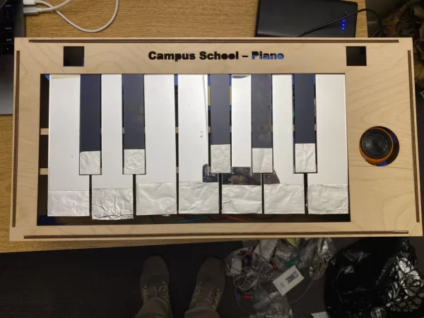
For my Campus School Assistive Tech Project, I made a realistic-looking touch-enabled piano that plays appropriately-determined tones when you press on each key.
This project utilizes an Arduino Nano RP2040 running CircuitPython as well as an MPR121 Capacitive Touch Sensor. The sensor uses a STEMMA QT connector to connect to the Arduino, which is mounted on top of a breadboard in order to easily connect cables. There is a small speaker connected to play sounds. Lots of the wiring is connected with alligator clips (for example, these connect the touchpads on the MPR121 to the tinfoil on the keyboard keys). Finally, the Arduino is connected to an external power bank I have so that the setup can run on its own power (standalone, doesn’t need to be connected to a laptop).
I wanted to build this project in particular because I am a piano player myself and remember how fun it was to mess around with electronic keyboards when I was really young (and I still enjoy doing so). I thought it was so cool we learned how to make something like this and wanted to build it for kids at the Campus School to share that joy I had when it came to keyboards and music. I also wanted to make sure it looked realistic and fun (so that’s why I spent a fair amount of time designing the wood and acrylic lasercut stencils by hand).
If you have any questions, don’t hesitate to reach out and I’ll try my best to answer – I’m [email protected].
Supplies
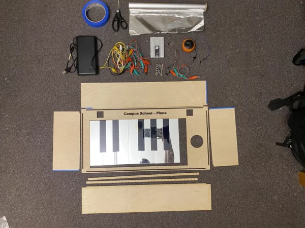
All materials:
- Circuits and wiring materials (middle of image):
- Arduino Nano RP2040 (can also substitute with Adafruit Circuit Playground Bluefruit or similar)
- Breadboard (for easily connecting the Arduino to the speaker and MPR121 sensor)
- MPR121 Capacitive Touch Sensor
- Speaker with aux out cord (you’ll clip alligator clips to the tip and sleeve)
- 14 alligator clips (12 to connect MPR121 touchpads to keys, 2 to connect speaker to Arduino)
- External battery pack or power bank
- USB 2.0 to Micro USB cable to connect external battery pack to Arduino
- Any other alligator clips or wires you need to connect all the above
- Frame and building materials (top and bottom of image):
- Wood frame to house the piano
- Acrylic keys (used 1/8″ “vanity” [mirrored] and 1/8″ dark blue acrylic in this project)
- Take to secure elements like the box sides and keys to create the frame
- Tinfoil (for the capacitive touch part, will be attached to the bottom of the keys)
- Scissors to cut the tinfoil (ripping works too but is much less clean)
Step 1: Lasercut and Assemble the Frame and Keys
First, design and lasercut the materials for the frame and keys. I designed this in Adobe Illustrator and went to my university’s Maker Space to cut this out (they were super nice and helpful).
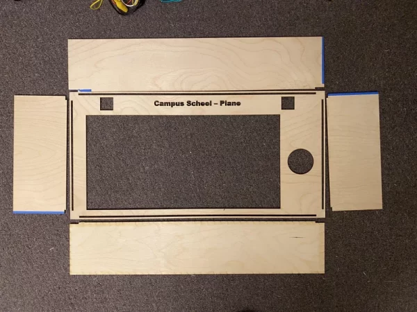
The frame I made out of wood (1/8″ birch wood I believe), and I made sure to include a hole for the speaker. Optionally, you can add volume control or pitch control potentiometers and I cut out two squares at the top for that. Make sure you include a hole for the keys so they can sit flush (make this bigger than you think as you’ll need to space the keys out so they don’t touch each other), and I also added some text at the top and cut that out too so it looks nice. I made sure the sides of the box could easily slot into slits I made in the top.
For the keys, I tried to make it look realistic, and so used a combination of alternating light and dark keys. I saw the vanity / mirrored acrylic and had to go with that for the white keys! The dark keys are the darkest acrylic I could find which was dark blue.
Assemble the wooden part of the box, which should be as easy as slotting in the sides into the notches on the top and then using tape to make sure everything stays together.
Then cut out some tinfoil to place at the bottom of each key. Wrap the tinfoil around each key, then place the keys next to each other in the proper pattern so you can attached them to the box. I found this was easiest done when the box was upside down. I also used two long thin pieces of wood to support the keys in place, which is critical. Use tape to secure everything down.
Once you have the box all good to go, it’s time to write the code that will run on the circuitry!
Contact me (email at the top and bottom of this Instructable) if you’d like for me to send you the Adobe Illustrator file I used to cut this design!
Step 2: Write the Code!
Now it’s time to write the CircuitPython code that will run on the Arduino Nano RP2040.
Let’s briefly walk through it line-by-line:
First, add your import statements for the libraries you’ll need for the project.
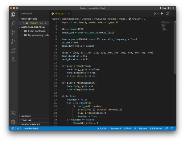
import time, board, pwmio, adafruit_mpr121
Then, add these lines to set up your touchpad (MPR121 Capacitive Touch Sensor).
i2c = board.I2C()
touch_pad = adafruit_mpr121.MPR121(i2c)
Next, add these lines to set up your Arduino with your external speaker.
tone = pwmio.PWMOut(board.D3, variable_frequency = True)
volume = 500
tone.duty_cycle = volume
Now, set up the frequency and duration for your tones that will play each time you touch a key.
notes = [262, 277, 294, 311, 330, 349, 370, 392, 410, 440, 466, 494]
tone_duration = 0.2
rest_duration = 0.01
Create a function that will be responsible for playing tones when it is called.
def play_a_tone(freq):
    tone.duty_cycle = volume
    tone.frequency = freq
Now that everything’s set up, let’s get to the main part of the code, explained below:
while True:
    touched = False
    for i in range(12):
        if touch_pad[i].value:
            print("Pad {} touched".format(i))
            play_a_tone(notes[i])
            touched = True
    if touched == False:
        tone.duty_cycle = 0
while True runs everything in this loop during the program’s execution in perpetuity.
- First, initialize the variable touched = false, so we know nothing’s playing at the moment.
- Next, we have 12 keys that play 12 notes (see the notes[] list), so let’s loop through them here.
- If a pad is touched…
- Then print that to the console (for debugging and visibility purposes)
- Also, run the function play_a_tone() we defined earlier, and pass in the pad / key that was touched
- Now set the variable touched = True because a key was just touched, a note is being played
- If touched = False, then we want to make sure nothing’s playing
- And that’s what happens with this line
Let me know if you have any questions about the code! Here it is in full:
import time, board, pwmio, adafruit_mpr121


i2c = board.I2C()
touch_pad = adafruit_mpr121.MPR121(i2c)


tone = pwmio.PWMOut(board.D3, variable_frequency = True)
volume = 500
tone.duty_cycle = volume


notes = [262, 277, 294, 311, 330, 349, 370, 392, 410, 440, 466, 494]
tone_duration = 0.2
rest_duration = 0.01


def play_a_tone(freq):
    tone.duty_cycle = volume
    tone.frequency = freq


def play_a_rest(duration):
    tone.duty_cycle = 0
    time.sleep(duration)


while True:
    touched = False
    for i in range(12):
        if touch_pad[i].value:
            print("Pad {} touched".format(i))
            play_a_tone(notes[i])
            touched = True
    if touched == False:
        tone.duty_cycle = 0

Source: Piano for Campus School Project With Arduino Nano RP2040 + MPR121
- How does the piano detect key presses?
The project uses an MPR121 Capacitive Touch Sensor connected to tinfoil attached to the bottom of the keys. - Can I substitute the main microcontroller?
Yes, the text suggests substituting the Arduino Nano RP2040 with an Adafruit Circuit Playground Bluefruit or similar. - What materials were used for the white and black keys?
White keys are made from vanity or mirrored acrylic, while dark keys use dark blue acrylic. - How is the device powered without a laptop?
An external battery pack or power bank connects to the Arduino via a USB 2.0 to Micro USB cable for standalone operation. - What software runs on the Arduino?
The project utilizes CircuitPython code written specifically for the Arduino Nano RP2040. - How many notes does the piano play?
The piano is programmed to play 12 distinct notes corresponding to the 12 keys. - What tool was used to cut the frame and keys?
A lasercutter at a university Maker Space was used to cut the wood frame and acrylic keys based on Adobe Illustrator designs. - How are the speaker wires connected?
Alligator clips are clipped to the tip and sleeve of the speaker's aux out cord to connect it to the Arduino.