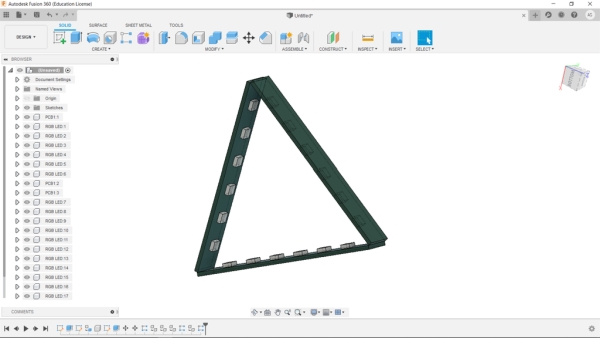
I’ve been a fan of Commerical Nanoleaf available in the market but their cost is pretty high so I try to make my own version by designing a WS2812B LED strip and connecting three of these strips together in a triangular shape to make a Nanoleaf like setup.
The goal here was to make a Cheap yet functional Nanoleaf like Light without using a 3D printer! one option was to make the Nanoleaf structure from Plastic Cardboard but it was a long and messy process that involves craft skills so I ditched that idea and made a super simple PCB version.
Supplies
These are the things that I used in this project
- WS2812B RGB LEDs x 18
- Custom PCBs which were provided by JLCPCB (JLCPCB you guys rocks!)
- Attiny85
- 100nF Capacitors SMD 0603 package x 18 (it’s recommended to use 1uF but I used 100nF and the setup worked fine)
- USB Micro port
- Solder paste
- SMT Hotplate
- 3D Printed Soldering JIG
Step 1: PCB Planning
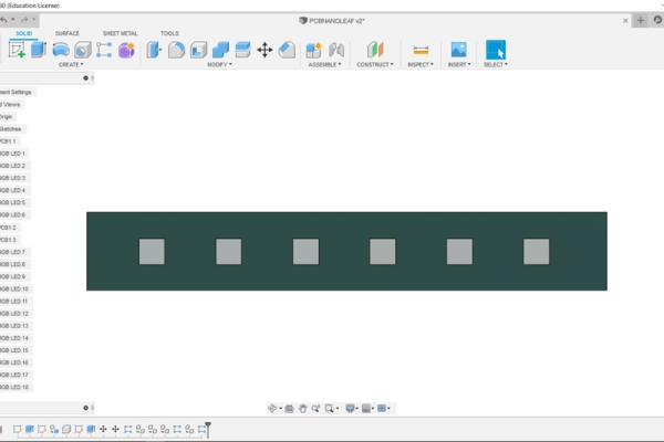
So in order to make this setup, I first prepared its basic setup which was 18 SMD WS2812B RGB LED Connected with an Attiny85 and a button powered by a USB Micro port.
I choose a simple attiny85 to control the RGB LEDs as this was just an experimental project for now.
If you guys want to avoid the hassle of remaking this project’s PCB, Ill leave the Gerber Data of this project’s PCB so you can send that to a PCB manufacturer for samples!
Also, PCBs for this project was provided by JLCPCB, JLCPCB you guys rocks!
it took a week for PCBs to arrive, after arriving I started the assembly process.
Step 2: Assembly
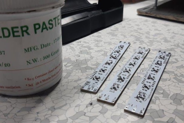
the assembly process is pretty simple, we just need to solder Ws2812B LEDs on PCBs and for that, I used an SMT reflow hotplate, which I made from a cloth iron’s element.
now the SMT soldering process is a bit different than a regular soldering process, in this process we need to add soldering paste to the pads of each component first.
the soldering paste is basically a mixture of solid miniature solder balls combined with flux to make a paste-like substance.
so we need to apply it on the components pad and then place the components on it one by one.
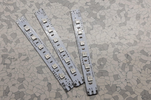
after that, we just need to plate the PCB on a preheated hot plate. hot plate temperature gradually increases up to 250-degree Celsius which is enough to melt the solder paste, after a few mins, we need to remove the PCB from the hotplate and cool it down.
Also, we need to prepare 3 LED Strip for Nanoleaf and 6 for Hexaleaf.
Step 3: Final Assembly
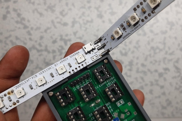
In order to solder this setup, I made Two Jigs that hold two PCBs together at an angle of 60 degrees for Nanoleaf and 120 degrees for Hexaleaf, I solder two PCBs together by adding solder wire between two Pads of PCB.
We have to connect VCC to VCC and GND to GND of all Strips together along with Dout of First Strip to Din of Second Strip, Dout of Second Strip to Din of Third Strip, Dout of Third Strip to Din of Fourth Strip, Dout of Fourth strip to Din of Fifth, and Dout of Fifth to Din of Sixth and that’s pretty much it.
Step 4: Wait, How Does This Setup Works?
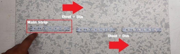
First Strip houses the Attiny85 setup, the Attiny’s D0 is connected with Din of Ws2812B LED.
First led is the starting point of this series. the Dout of the first strip is hooked up with Din of the second Strip and its Dout is connected with Din of the Third strip.
I have placed the Shorting resistor Pad in the strip LED strip which is connected in between Din of First LED of the FIrst strip, so if I want to control the strip with onboard Attiny, I just need to add a zero ohms resistor on that pad to short the connections.
Step 5: Uploading Code
For Flashing the code and burning the bootloader of Attiny85 MCU, I use my Arduino ISP programmer which I made especially for programming attiny85.
Check out More about this project from here-
https://www.instructables.com/Multiple-ATtiny8513A…
we need to connect its SPI pins with SPI pins of Attiny85 which are
- MISO
- MOSI
- SCK
- RESET
- VCC
- GND
after connecting the SPI pins, select the Attiny85 in Board manager, then change the Programmer to “Arduino as ISP” and hit Burn Bootloader, wait for few seconds and you will see a “DONE BURNING BOOTLOADER” message.
After this, we can upload the code to our Attiny85 MCU just by going into TOOL>Upload using Programmer. Code is a basic Rainbow sketch and the Din of First Pixel is connected with the Attiny’s D0 pin.
Watch the videos below for Test run!
Step 6: Test Result/Video
Source: PCB NANOLEAF/HEXALEAF