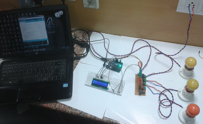
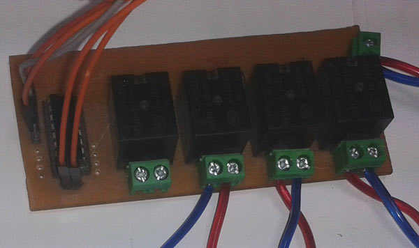
This project explains designing a home automation system which is controlled by a computer to switch On and switch Off various electrical and electronics devices. For demonstration we have used 3 zero watt bulbs which indicates LIGHT, FAN and TV. It uses Arduino Uno board as a controller and a 5V relay to connect light bulbs with the circuit.

There could be various types of communications to control devices like home appliances, industrial appliances, etc. Broadly we can categorize them as wired and wireless. For example in wireless communication we transmit signal using radio frequency (RF) and in wired communication we use wires. Wired communication can further be categorized as:
Parallel communication
Serial Communication
In parallel communication we use many wires depending on the data size in bits, i.e. if we need to transmit 8 bit then we would need a 8-bit wire. But in serial communication we only used two wires for transmitting data and receiving data as in serial communication data are transmitted serially i.e. bit by bit.
Components Required
Arduino UNO
Serial Cable
ULN2003
Relay 5 volt
Bulb with holder
Connecting wires
Bread board
16×2 LCD
Laptop
Power supply
PVT
Relay
We need a relay to connect the circuits with higher voltage AC appliances like bulb, TV, fan, etc. Relay is a kind of switch which is used for electronic to electrical interfacing. Relays contain a coil and some switching contact cores. There are different types of relays, like:
Single Pole Single Through ( SPST ).
Single Pole Double Through ( SPDT ).
Double Pole single Through ( DPST ).
Double Pole Double Through ( PDT ).

Here we have used single pole double through (SPDT) relay. SPDT relays contain five pins, in which 2 pin for coil and one is for pole and other two are namely “Normally Connected” (NC) and “Normally Open” (NO).
Circuit Diagram and Explanation
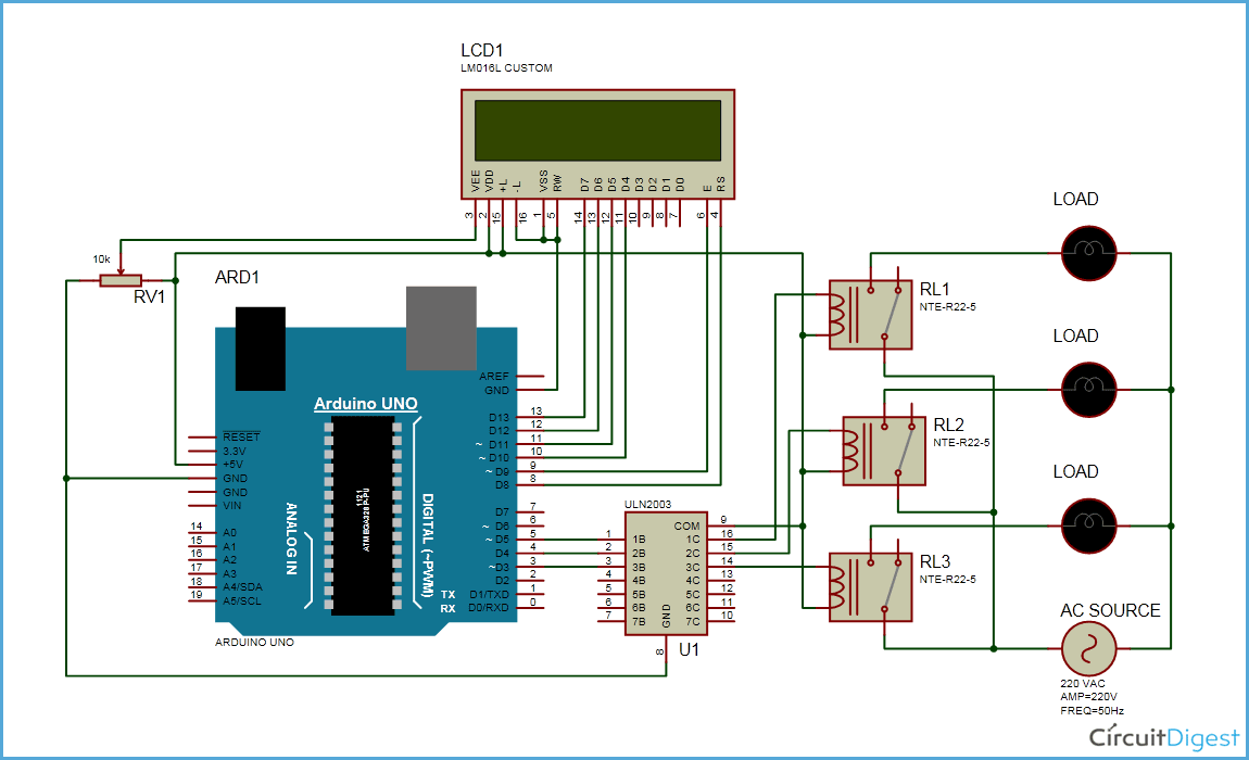
As shown in the above schematic diagram above, a 16×2 LCD module is used for displaying status of home appliances which is directly connected to arduino in 4-bit mode. Data pins of LCD namely RS, EN, D4, D5, D6, D7 are connected to arduino digital pin number 7, 6, 5, 4, 3, 2. For sending commands to arduino from laptop or PC we uses USB cable that we used for uploading program into arduino. And a relay driver IC ULN2003 is also used for driving relays. 5 volt SPDT 3 relays are used for controlling LIGHT, FAN and TV. And relays are connected to arduino pin number 3, 4 and 5 through relay driver IC ULN2003 for controlling LIGHT, FAN and TV respectively.
Here serial communication is used to control the home appliances. We send commands like LIGHT ON, LIGHT OFF, FAN ON, FAN OFF, TV ON AND TV OFF to control AC home appliances. After receiving the given commands, arduino send signal to relays which are responsible for switching on or off of the appliances.
When we press ENTER after typing one of any given command on hyper terminal or serial terminal, arduino performs relative task like turning on the “fan” and likewise other tasks. And a relevant message is also displayed on 16×2 LCD which is programmed in the code. (See the code section in bottom)
Read More: PC Controlled Home Automation using Arduino

