
Summary of The open source hardware and software OLED Watch
The author's journey began with an Arduino UNO and a bedside clock project, leading to the discovery of the compact Femtoduino. Combining this with Sparkfun's ring of 16 LEDs, they designed their first OLED watch. The process involved learning Fritzing for PCB design and utilizing OSHPark for fabrication. Despite initial errors in the v1.0 layout requiring a redesign, the author successfully created a functional, self-taught wearable device using open-source hardware and software.
Parts used in the OLED Watch:
- Arduino UNO
- Tiny breadboard
- Protoshield
- 4 digit 7 segment display
- DS1307 RTC chip
- Femtoduino board
- Ring of 16 LEDs
- Battery holders
- Switches
- Circuit board (PCB)
Introduction
It all started two years ago when I first found this thing called an Arduino. I had seen some projects online people had made with one, so I impulse bought an Arduino UNO, knowing nothing about what it was or how it worked, but only that I wanted to learn. As soon as it arrived, I bought a tiny breadboard and ran the blink sketch on an LED. I began to get the hang of the code, and bought a projects book to get started with my own projects. Combining several examples together, my first project was my current bedside clock built onto a protoshield on the UNO, a 4 digit 7 segment display, and a DS1307 RTC chip. This project was my first experience with reading datasheets, digikey, soldering, and my first step towards the watch that I never dreamed I would design.
With this little experience under my belt, I had actually made something. It felt great. I had never really known this before, but building something that’s practical, useful, looks cool, and you’ve made yourself was awesome. I wanted to do that a lot more. After finishing the clock, I stumbled upon a tiny board that was Arduino compatible, and that because of its relation to the small amount of electronics knowledge I had accumilated, looked friendly enough to take a chance at getting into. By far the most attractive feature of this board was its tiny, tiny size, a mere 2cm x 1.5cm, and the name of that very important board that is in almost everything I do now was the Femtoduino.
(Fun Fact: I’ve since become great friends with the Femtoduino guys and have taken many of the product pictures you’ll see on Femtoduino.com including this one!) In another impulse buy, I purchased one of these minuscule Arduino boards and started the beginnings of what would become my first watch experiment, v2.1. At the same time, I found a website called Sparkfun.com that sold battery holders, switches, and other watch related parts, including the led display I wanted to use, an oddly packaged ring of 16 LEDs that captured my attention and came in an array of glowing colors, the likes of which I had never seen before.
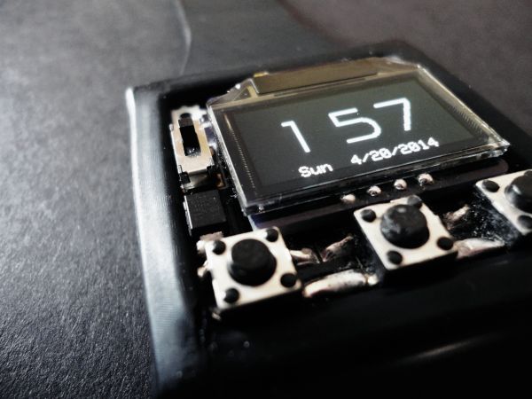
After seeing these two products on the same day, I was set on making a watch with them, however hard it would be, and vowed to teach myself all the code/design skill needed to accomplish it. Like any electronic product, in order to provide structural integrity and a substrate on which to connect all of the electrical components together in the right way, I was going to need to design a circuit board. In my search to find the best software to use as a beginner on a Mac (which makes a big difference btw), I found Fritzing, a drag and drop, easy to use, free pcb design tool, that I still use today as it is really quite advanced but is inviting to beginners as well. Check out the referrals page for more. I taught myself the ropes, and I designed my first pcb, v1.0. I then searched for a pcb fabricator to make and ship me my design, and discovered OSHPark, an ingenuous service that can get the highest quality gold plated pcbs into your hands in two weeks at very cheap prices made in the US. Check the referrals page for them too. When the first version came back from OSHPark, I realized I had made a grave mistake. I had broken out the programming pins of the Femtoduino (the original without USB support) underneath where the board was mounted (facepalm) so I had to reroute and try again. After some testing and trial and error, and some self taught coding sessions, I came up with this design, the first of my watches. Even though the battery only lasted about a month before it couldn’t support the Femtoduino, it worked.
For more detail: The open source hardware and software OLED Watch
-
What was the author's first project?
The author's first project was a bedside clock built onto a protoshield on the UNO using a 4 digit 7 segment display and a DS1307 RTC chip. -
Why did the author choose the Femtoduino?
The author chose the Femtoduino because of its tiny size of 2cm x 1.5cm and its friendly nature relative to their small amount of electronics knowledge. -
Where did the author find the LED display?
The author found the oddly packaged ring of 16 LEDs at a website called Sparkfun.com which also sold battery holders and switches. -
What software did the author use to design the PCB?
The author used Fritzing, a drag and drop, easy to use, free pcb design tool available for Mac users. -
Which service was used to fabricate the circuit boards?
The author used OSHPark to make and ship gold plated pcbs into their hands in two weeks at very cheap prices. -
What mistake was made during the first PCB version?
The author broke out the programming pins of the original Femtoduino underneath where the board was mounted, requiring a reroute. -
How long did the battery last in the first working watch?
In the first working watch, the battery only lasted about a month before it could not support the Femtoduino. -
What type of chips were used in the bedside clock project?
The bedside clock project utilized a DS1307 RTC chip along with a 4 digit 7 segment display.
