Summary of Does your op amp oscillate?
The article reviews common causes of operational amplifier oscillation and practical remedies. It explains amplifier basics: inputs drive a transconductance (gm) block feeding a gain node, buffered to the output, with compensation capacitor Cc dominating frequency response. Because op amps lack a single ground reference, Cc currents return via supply rails. A current coupler divides drive between output transistors, producing two effective Cc/2 elements that set response. The piece highlights load interactions, feedback network design, supply bypassing, and one-port input/output self-oscillation as typical instability sources.
Parts used in the[Does your op amp oscillate?]:
- Operational amplifier (non-rail-to-rail op amp)
- Inputs (input transistors forming gm block)
- Transconductance block (gm)
- Gain node
- Compensation capacitor Cc
- Current coupler (splits drive current)
- Output transistors (top and bottom outputs)
- Supply rails (positive and negative supplies)
- Output buffer
- External feedback network
- Supply bypass capacitors
We analog designers take great pains to make our amplifiers stable when we design them, but there are many situations that cause them to oscillate in the real world. Various types of loads can make them sing. Improperly designed feedback networks can cause instability. Insufficient supply bypassing can offend. Finally, inputs and outputs can oscillate by themselves as one-port systems. This article will address common causes of oscillation and their remedies.
Some Basics
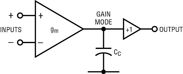
Figure 1a shows the block diagram of a non-rail-to-rail amplifier. The inputs control the gm block which drives the gain node and is buffered at the output. The compensation capacitor Cc is the dominant frequency response element. The return of Cc would go to ground if there were such a pin; however op amps traditionally have no ground and the capacitor current will return to one or both supplies.
The input gm’s output current is sent through a “current coupler” that splits the drive current between the output transistors. Frequency response is dominated by the two Cc /2s, which are effectively in parallel. These two topologies describe the vast majority of op amps that use external feedback.
For more detail: Does your op amp oscillate?
- What are common causes of op amp oscillation?
Common causes include various types of loads, improperly designed feedback networks, insufficient supply bypassing, and inputs or outputs oscillating as one-port systems. - How does the compensation capacitor Cc affect frequency response?
Cc is the dominant frequency response element and controls the amplifier's dominant pole behavior. - Where does the return current of Cc go in an op amp?
Because op amps traditionally have no ground pin, the capacitor current will return to one or both supply rails. - Why are there effectively two Cc/2 elements in many op amps?
The input gm output current is split by a current coupler between the output transistors, making two Cc/2 elements that are effectively in parallel and dominate frequency response. - Can improper feedback network design cause instability?
Yes, improperly designed feedback networks can cause instability and lead to oscillation. - How can insufficient supply bypassing lead to oscillation?
Insufficient supply bypassing can offend the amplifier and contribute to instability and oscillation. - Do inputs and outputs ever oscillate by themselves?
Yes, inputs and outputs can oscillate by themselves as one-port systems. - What role does the current coupler play in amplifier behavior?
The current coupler splits the drive current between output transistors, affecting frequency response through the effective Cc/2 elements.