Summary of Omnik Inverter Off It’s Cloud and on My MQTT
This project improves an Omnik solar inverter by disabling its mandatory cloud connection and enabling MQTT data reporting using a Wemos D1 (ESP8266). The inverter's WiFi is secured and isolated from the home network, preventing it from "phoning home." The Wemos periodically connects to the inverter's WiFi, retrieves data via a reverse-engineered protocol, and then publishes it as MQTT messages to the home broker. This method provides privacy and integration with home automation, without additional wiring and at low cost.
Parts used in the Omnik Inverter MQTT Gateway Project:
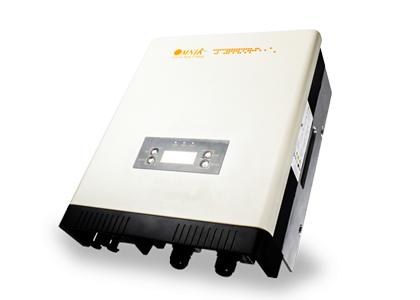
- Omnik inverter with WiFi module
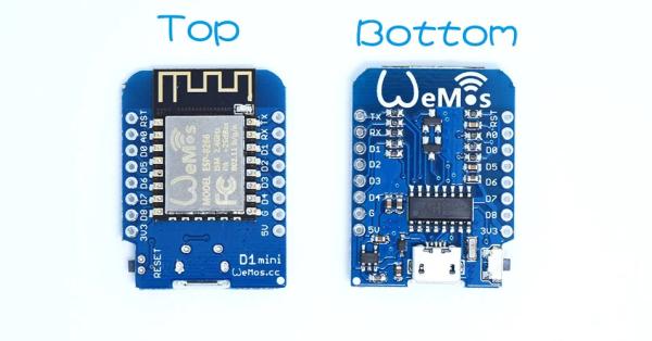
- Wemos D1 (ESP8266 development board)
- USB power supply
- USB to mini-USB cable
- Computer with Arduino IDE and ESP8266 support
I have a solar power installation using an Omnik string inverter. Omnik is a China based manufacturer of PV inverters and they make extremely efficient devices. Optionally, you can install a WiFi module to make it “connected”. I am very content with the device, with two notable exceptions.

- It “phones home” to a China based cloud service and as long as the device is connected to the Internet, this cannot be switched off. I don’t like that.
- The inverter has no decent documented API (nor does cloud service). As home automation and IoT devices are gravitating towards MQTT messages, I wanted it to send MQTT messages.
For this project, which solves both issues, we turn towards our picky but reliable friend the ESP8266. I used a Wemos D1, but any incarnation you like can be used. The plan is to:
- Not give the WiFi module of the inverter any credentials to the home WiFi network. This solves problem 1.
- Let the Wemos periodically connect to the Access Point of the Inverter to acquire the data that we want. We can use the reverse engineered non-web protocol for that. I used this code as a starting point.
- Then disconnect, connect to the home network and publish said data as an MQTT message.
Our bill of material is extremely simple:
- One Wemos D1, to be purchased through the Wemos website or your favorite auction site;
- One USB power supply with a USB-mini cable.
There is no wiring needed at all. The cost is below 10 EUROs.
I assume you already have
- an Omnik inverter with a WiFi module installed;
- an MQTT infrastructure (broker, dashboard);
- a recent version of the Arduino IDE with support for the ESP8266 processor installed.
- some familiarity with the above.
There are quite a few instructables about MQTT and using the Arduino IDE for an ESP8266 processor, but feel free to ask away in the comment section.
Step 1: Disconnect the Omnik From the Internet Permanently

If, like me, you had the inverter connected to your WiFi network, it’s surprisingly hard to disconnect it. Any change you make to the WiFi settings is checked before it is applied. Instead of jumping through hoops such as changing the encryption password of the router and the inverter, then changing back the router, I decided to take a cleaner approach and start from scratch.
Go to the inverter and perform the following actions:
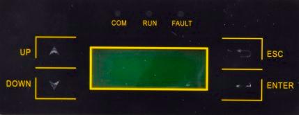
- press the Down button until Set blinks, then press Enter
- Press the Down button until WiFi blinks, then press Enter
- Press the Up button so that Yes blinks, then press Enter
Connect to the inverter
Open your computer and find a WiFi network called AP_xxxxxxxx, the x’s presenting digits. Connect to it. Depending on the operating system you might first need to make it “forget” that network if you have connected to it before, as now a possibly stored WiFi password is gone.
Secure the access point of the inverter
Once connected, open your browser, enter 10.10.100.254 and press Enter. A login popup will appear. Enter admin in both fields to log in. Do NOT follow the wizard and configure the access point. Click on Advanced in the left hand menu, then the submenu Wireless point.
Make the following changes:
- Encryption method to WPA2PSK
- Encryption type to TKIP
- Enter a WiFi password. Write down the password, you will need it to connect to the inverter soon.
Click Save and the WiFi module will restart. You will loose the connection as it now requires the password. Reconnect, and enter the WiFi password. Again, you might need to make your PC “forget” the AP_xxxxxxxx network first. You should now be connected to the inverter again over a secure WiFi link.
Secure the configuration pages of the inverter
Open your browser, enter 10.10.100.254 and press Enter again. A login popup will appear. Again enter admin in both fields to log in. Click on Account in the left hand menu. Change the username and the password to two unique, non trivial strings. You will have to enter both of them twice. Write them down. Click Save and the WiFi module will restart. Wait a few seconds and reload the page. Verify that you now need the new username and password to open the configuration pages. Your inverter now has an extra layer of security against changes made by outsiders.
This concludes all the work that has to be done on the inverter. It is now disconnected from the Internet, reasonably secured, but it still acts as a WiFi Access Point we can use to query it.
Step 2: Download and Configure the Software for the Wemos D1

Download the software for the Wemos. You can find the code here. You need to make a few changes to configure it for your home network and your inverter
- homeSsid: the name of your home WiFi network
- homePassword: the password of your home WiFi network
- omnikSsid: the name of your Omnik WiFi network. It should look like AP_xxxxxxxxx
- omnikPassword: the password of your Omnik WiFi network you assigned in the previous step
- omnikIP: the IP address of the inverter. This is always {10, 10, 100, 254}
- omnikCommand: the byte string required to query your inverter, see below.
- mqtt_server: the hostname of your MQTT broker
- mqtt_port: the TCP port number, usually 1883 for insecure or 8883 for secure (SSL) connections
- mqtt_username and mqtt_password: the credentials for your MQTT broker
- mqtt_clientID: enter some random digits here
- mqtt_outTopic: the topic of the MQTT messages.
The omnikCommand byte array is specific for your individual inverter. I published a small tool as a Google spreadsheet to compute the string. You need to input the serial number (around 10 decimal digits) in cell B1 and use the string calculated in cell B4 in your sketch.
To successfully compile the code you also need the PubSubClient.h library. Make sure the proper board (Wemos D1) and port is selected, then upload the sketch to the board. You can put the little Wemos board in a little plastic container for protection and connect it to the USB power supply. Put it somewhere not too far from both the inverter and your WiFi router and you are set!
The main loop in the software connects to the inverter WiFi, then makes a TCP connection to it, reads the data, disconnects, connects to the home WiFi network, then to the MQTT broker, and publishes the reformatted data there. It takes just under 15 seconds to do all this connecting and disconnecting. After that, there is a delay of 20 seconds, so the data should be published roughly every 35 seconds.
Step 3: A Few Words About the Messages, the Broker and Testing

The code outputs a bit of debugging data, so if something is not working, simply hook up the WeMos to your PC again, start the Arduino IDE and press CTRL+SHFT+M to start a serial console. Make sure the speed is set to 115200.
You can either use your own broker, or use a cloud based service. I run my own, Mosquitto installed on my Synology NAS. If you are OK with a cloud service, you can use Adafruit or Amazon AWS or any other one.
The messages are JSON strings formatted like this:
On boot the following message is published:
{“reset”:true, “version”:”20170727a”}
This can be used to detect unexpected reboots.
Normal messages look like this:
{“acPowerNow”:580,”acVoltageNow”:233.8,”acCurrentNow”:2.5,
“dcVoltage”:410.8,”dcCurrent”:1.4,”frequency”:49.96,
“energyToday”:12.16,”energyTotal”:6082.7,
“temperatureHeatsink”:32.5}
Power in watts, voltages in Volts, currents in Amps, frequency in Hertz, Energy in kiloWatthours and temperature in degrees Celsius.
I use mosquitto_sub to check the messages.
mosquitto_sub -h hostname -t “Solar/Omnik” -u user -P password -p 1883 -v
See the screen grab for the results. All messages are published with the retain flag set to true.
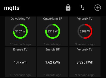
On my phone I use an app called MQTT Dash and I have included a screen print and what to enter to show that green power dial.
Source: Omnik Inverter Off It’s Cloud and on My MQTT
