Summary of NXP Kinetics Smart Web Multimedia IoT – Flexduino Platform
The article describes "Flexduino," an Arduino-compatible platform using the NXP K82 Cortex-M4 MCU and FlexIO technology to handle high-speed multimedia. It enables web-based video streaming (QQVGA at 7 fps) and audio playback via WiFi. The project integrates a custom shield board with specific sensors and modules, running on the KSDK with ported libraries for file systems, TCP/IP, and web servers, offering both advanced debugging and easy coding styles.
Parts used in the Flexduino:
- NXP Kinetis Freedom Board with FlexIO
- ATMEL WINC1500 WIFI MODULE
- OV7670 CAMERA MODULE
- WM7236 MEMS MICROPHONE
- micro SD card socket
- LM386 amplifier
- Cirrus Logic WM7236E development board
Hardware components:
| NXP Kinetis Freedom Board with FlexIO |
×1
| ATMEL WINC1500 WIFI MODULE |
×1
| OV7670 CAMERA MODULE |
×1
| WM7236 MEMS MICROPHONE |
×1
STORY
ABSTRACT
The project aim is to build an Arduino like development environment that takes advantage of FlexIo advance driver module to build new drivers and interface with high speed multimedia devices such as camera, digital microphones, among others. This project will show how the K82 Cortex M4 MCU with FlexIO technology will allow to build a new level of designs that requires multimedia information handling such as image and audio, while maintaining a level of performance not seeing before for an Arduino compatible platform. The software platform with ported libraries that forms the called “Flexduino” platform offer many benefits for different expertise users, advance users will benefit from highly customizable hardware and advance debugger of Kinetics SDK for the most demanding tasks while entry level users will felt comfortable with arduino like coding style. A complete demonstration of the presented work is a web video QQVGA running at 7.0 fps while doing audio playback using DAC. FlexIO module was using to implement a MEMS microphone digital driver capable of running in the “background” too. TCP/IP server is used to host the video and example jQuery/javascript by means of WiFi IC WINC1500, that in conjunction with K82 MCU achieves 1.65 Mbps without DMA during tests.
PLATFORM OVERVIEW
Rather than giving an introduction of FlexIO and FRDM-K82F board and features, it will be presented the developed hardware and software with clarification of techniques and implementation carry out to bring this project to life, readers are kindly referred to NXP website for documentation. The next section will cover the Hardware followed by software, since an understanding of the first one might be required to understand the code.
The Flexduino Logo to start.
HARDWARE OVERVIEW.
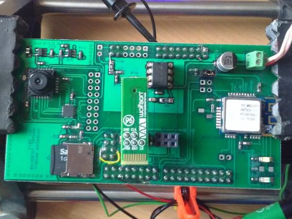
The FRDM-K82F design was perfect for this integration with Arduino platform because it provides a similar footprint, nonetheless the different electrical interfaces required for this project makes imperative to build a custom shield board in order to provide:
- WiFi module
- micro SD card
- MEMS digital microphone
- Audio output circuitry
- Camera Interface
The last item above was not necessary since the K82 devel board has an expansion connector for OV7670, still a new camera interface was implemented in hardware explained further on in next section.
The following picture shows the TOP view of shield. MEMS sensors used are in a very nice development board to worry less about signal integrity.
TCP/IP connectivity – WiFi to the rescue.
In order for transmit multimedia this days in a modern style, WiFi was the preferred choice, specially for a web cam with built in audio, the WiFi options are not as many as the wired ones, but a good one with Arduino support is to use WINC1500 IC. A module was used to speed hardware design. The interface with K82 was done using SPI module and during the tests it works at even 48MHz, but it was notice that above 40MHz there was no improvement in bandwidth during tests using netperf.
File System – micro SD card are getting cheaper this days!
A micro SD card push pull socket in on top of the custom shield to provide the platform File system. The connection was made by SPI second module available in K82 MCU. An astonishing read and write speed was conceived with this MCU using bare metal. Bellow is some statistical data, the test can be enable or disable in code and execute at start up. As you might guess the speed is very dependent on the SD card used, different cards were tested and the best one (SandDisk 1GB) is shown below.
WRITE TOOK 73 ms, rate = 4383.56 kbit/s
READ TOOK 70 ms, rate = 4571.43 kbit/s
Audio Recording – Let’s see of what is done the FlexIO 🙂
The digital MEMS sensor used was a Cirrus Logic Part number WM7236E device, The interface consist of a CLK and a data signal DAT. The audio samples comes modulated as pulses by some internal 1 bit ADC, this is know as PDM. The difficult thing is that you need to acquired large amount of data at relative high speed and do some filtering and decimation, that thanks to a brilliant mind that invent the CIC filter nowadays we can implement this in C. Of course don’t forget that here FlexIO is mandatory. Since this is a about to have a development environment for further experiments, the shield board includes two interfaces for Left and Right channel. One nice feature of this sensors is that they can share the Data line and it’s the task of the driver to sample at the correct clock edge each channel, a simple task for FlexIO module! Since we want to experiment with voice on this project, the selected sample frequency of MEMS was fixed at 500 KHz, enough to get 16 bit PCM samples out of it at 8000 Hz after CIC stage.
In this project a development board from Cirrus logic was used. Very nice little board to try.
Audio Output stage. Let’s try the 12-bit DAC.
The DAC was used as output device, the nice thing of this highly advance module is it’s DMA capability. The DAC output is connected to an ampliflier stage made by the legendary LM386 amplifier, input filter and output filter is provided as well as gain control. A separate Analog Ground was implemented joined at a single point in PCB and of course bypassing caps all the way around. Besides this precaution, it was notice that some noise get’s amplified during highly processing tasks such a file transferring using web browser. It’s suspected that the 10K potentiometer at input stage used for volume control is picking up some noise from RF, but nothing that cannot be fixed in a second hardware revision.
Camera Interface – Push the limits but step by step.
The shield board has an on board CMOS sensor connected to a serializer LVDS IC, the idea was to explore FlexIO capability to handle LVDS signal at high speed. This will allow designer to place the camera far away from CPU perhaps using a Flex cable. Something not possible (at least for commercial use case) by means of the parallel interface. Since the contest was to short in time, this end up in a hardware not tested. But to keep progressing with application, the popular OV7670 module was used and guess, FlexIO again to the rescue.
About the prototype.
The PCB is a double layer PCB with components on the TOP only. I did a mistake on the routing, specifically the error was the orientation of the double header connectors. Fortunately it was prototyped by hand and fix it in a couple of hours or less. The schematic show the connections as they are indeed. Only the VREF capacitor that I miss and need to be in order to use it, a 100 nF 0402 capacitor was placed between two pins of connector (find it in picture if you can!)
SOFTWARE OVERVIEW.
The software was developed under the KSDK, it was preferred this platform since the learning curve of eclipse like IDE was not present and also because of free available tools.
Similar to the above hardware sections will follow to detail the design of software, pointing to the different libraries used to implement each feature as well as it’s usage.
File System.
Instead of trying to port the arduino SD card libraries, a port of Elm Chan Fat FS is provided. This library is embedded iconic and very robust in my opinion. The only problem is that it doesn’t mimic arduino style of SD library, I wouldn’t worry about it as in other projects I have use it but for Flexduino it was better to find a solution. I came to a C/C++ wrapper library made for Elm Chan and arduino.
The library was ok but I modified to allow multiple files to be opened at the same time like is the case of Fat FS library.
Usage is explained below.
To open a file
if (fname) {
    Serial << F("Creating ") << fname << "\r\n";
    fh = file.open(fname, FA_WRITE | FA_CREATE_ALWAYS );
    free(fname);
 }
Notice that you need to keep track of the file handler you have opened so you can close it later.
To write for example
if (file.isOpen(fh)) {
    file.write(fh, buffer, size);
    total_size += size;
}
And finally close it
   file.close(fh);
   fh = -1;
I always end up deferencing the handler buy writing -1 as this value is not valid. For sure this library can be made better but it works really works for our case.
WiFi Module.
As a good engineer never start something from scratch unless there is no way ;), the Atmel WINC1500 has a binary blob inside that is proprietary but there is a C library with API provided by them to use with it. Different things were done in order to port the library for Kinetics platform, first the low level SPI driver interface followed by some timer functionality needed by the upper layer stack. Arduino make use of millis() function so why not do the same right.
Here is a extract of SPI bsp driver port file (nm_bsp_wrapper_mk82f.c), located under the bsp_wrapper source folder, it shows the initilization of SPI nm_bus_init and the spi_rw function that writes data to the bus.
static sint8 spi_rw(uint8* pu8Mosi, uint8* pu8Miso, uint16 u16Sz)

{
	dspi_transfer_t masterXfer;
	uint8 u8Dummy[TRANSFER_SIZE] = {0U};
	memset(u8Dummy, 0, sizeof(u8Dummy));
	if (!pu8Mosi) {
		pu8Mosi = &u8Dummy[0];
	}
	else if(!pu8Miso) {
		pu8Miso = &u8Dummy[0];
	}
	else {
		return M2M_ERR_BUS_FAIL;
	}
/* Start master transfer */
masterXfer.txData = pu8Mosi;
masterXfer.rxData = pu8Miso;
masterXfer.dataSize = u16Sz;
masterXfer.configFlags = kDSPI_MasterCtar0 | WINC_DSPI_MASTER_PCS | kDSPI_MasterPcsContinuous;
DSPI_MasterTransferBlocking(WINC_DSPI_MASTER_BASEADDR, &masterXfer);
	return M2M_SUCCESS;
}
/*
*	@fn		nm_bus_init
*	@brief	Initialize the bus wrapper
*	@return	M2M_SUCCESS in case of success and M2M_ERR_BUS_FAIL in case of failure
*/
sint8 nm_bus_init(void *pvinit)
{
	sint8 result = M2M_SUCCESS;
	/* Structure for SPI configuration. */
	dspi_master_config_t masterConfig;
	uint32_t srcClock_Hz;
/* Master config */
masterConfig.whichCtar = kDSPI_Ctar0;
masterConfig.ctarConfig.baudRate = TRANSFER_BAUDRATE;
masterConfig.ctarConfig.bitsPerFrame = 8U;
masterConfig.ctarConfig.cpol = kDSPI_ClockPolarityActiveLow;
masterConfig.ctarConfig.cpha = kDSPI_ClockPhaseFirstEdge;
masterConfig.ctarConfig.direction = kDSPI_MsbFirst;
masterConfig.ctarConfig.pcsToSckDelayInNanoSec = 100;
masterConfig.ctarConfig.lastSckToPcsDelayInNanoSec = 100;
masterConfig.ctarConfig.betweenTransferDelayInNanoSec = 0;
masterConfig.whichPcs = kDSPI_Pcs1;
masterConfig.pcsActiveHighOrLow = kDSPI_PcsActiveLow;
masterConfig.enableContinuousSCK = false;
masterConfig.enableRxFifoOverWrite = false;
masterConfig.enableModifiedTimingFormat = false;
masterConfig.samplePoint = kDSPI_SckToSin0Clock;
srcClock_Hz = CLOCK_GetFreq(DSPI_MASTER_CLK_SRC);
DSPI_MasterInit(WINC_DSPI_MASTER_BASEADDR, &masterConfig, srcClock_Hz);
	return result;
}
Other relevant functions of the port are located under the bsp folder, for example the winc1500 uses an interrupt ping to inform MCU of task completion, so the function init_chip_pins configure the interrupt and also the reset pin. Timer function nm_bsp_sleep is there to provide milliseconds blocking delay, that is made using PIT timer as shown below.
void _delay_ms(int time)
{
	/* Set timer period for channel 1 */
	PIT_SetTimerPeriod(PIT, kPIT_Chnl_1, MSEC_TO_COUNT(time, PIT_SOURCE_CLOCK));
	/* Start channel 1 */
	PIT_StartTimer(PIT, kPIT_Chnl_1);
	while(!PIT_GetStatusFlags(PIT, kPIT_Chnl_1));
	PIT_ClearStatusFlags(PIT, kPIT_Chnl_1, PIT_TFLG_TIF_MASK);
	PIT_StopTimer(PIT, kPIT_Chnl_1);
}
Another important thing was to provide functionality to the debug function of library M2M_DBG, in order to print to the console useful error conditions. Is important to note that the version of Atmel/Arduino WINC1500 library of this project uses the latest version of atmel ASF and WiFi101 arduino library. Last one is the upper layer software to provide TCP/IP and UDP. Some issues with those libraries were found, those were mostly fixed during the project without waiting for a mainstream update, for more info you can see this and this.
About the TCP/IP server libraries.
A very complete port of libraries is available for the new born Flexduino platform. Following figure shows a folder structure that might explain itself for arduino fans.
Notice the supporting libraries such Print, WString, Stream, etc that makes this highly attractive to use existing libraries from the Arduino ecosystem.
Most of the basic supporting libraries for connectivity like TCP, UDP, and the upper layer Client and Server are located under the winc1500 folder.
WebServer. The very nice TinyWebServer library now at your fingertips 😉
This library have been my favorite for c/c++ embedded platforms that don’t provide an integrated networking stack, I discover it years ago and now I ported to Flexduino platform, also have made some contribution by adding a souple of changes. Perhaps the demo app for the camera doesn’t show all it’s features (there is a video below), but the library makes very easy to deploy a web server, specially a jQuery/javascript one, because there is an uploader functionality using PUT command, that makes it easy to upload files to the SD card without having to remove it from embedded hardware. I used this couple of curl command to upload and delete files.
upload worker.js file
curl -0 -T worker.js http://192.168.1.60/upload/
and delete as needed
curl http://192.168.1.60/remove/worker.js
Of course you should restrict that functionality for production.
Also it has some modifications to allow submitting Forms. Without those nice features, the web road wouldn’t be so pleasant. It took me dozens of iterations of debugging HTML5 websockets that requires to changes those scripts.
The webserver menu is shown below. It uses jQueryUI menu, so we load javascript/jQuery only once while navigating the web site.
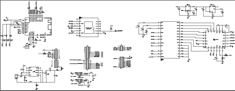
Schematics of NXP Kinetics Smart Web Multimedia IoT – Flexduino Platform
And this is printed in console at start
Initializing Flexduino Platform – NXP contest!
INIT SPI PORT for SD card completed
966 MB total drive space.
968 MB available.
SD card mount OK
WRITE TOOK 74 ms, rate = 4324.32 kbit/s
READ TOOK 69 ms, rate = 4637.68 kbit/s
<dir> System Volume Information
  5541 camera.html
 40960 Data.bin
  4158 favicon.ico
 22184 flexduino.png
  2734 hacksterio.png
   289 home.html
 38466 image.bmp
  5033 index.html
273199 jquery.js
816452 male.raw
126562 moh_8sec.raw
  7825 nxp.png
   984 nxpcss.css
  1801 pagelinks.js
   349 settings.html
 80002 sine_1000Hz.raw
  9899 test.jpeg
   346 voice.html
  1497 worker.js
   778 about.html
  1696 menu.html
 94080 record.raw
<dir> .Trash-1000
(APP)(INFO)Chip ID 1503a0
(APP)(INFO)Firmware ver   : 19.4.4
(APP)(INFO)Min driver ver : 19.3.0
(APP)(INFO)Curr driver ver: 19.3.0
Attempting to connect to SSID: MOOI
SSID: MOOI
IP Address: 192.168.1.60
signal strength (RSSI):-36 dBm
Websockets – Highly needed for transferring binary data.
A web sockets library was ported to allow binary data transfer, the idea is to use the last additions to HTML5 or any other kind of browser websockets library to transfer the digital image as binary data, it will allow to do it right and fast.
Here is a snippet that shows the library API callback where a developer do it’s magic.
Read More: NXP Kinetics Smart Web Multimedia IoT – Flexduino Platform
- What is the main goal of the Flexduino project?
The aim is to build an Arduino-like development environment that uses FlexIO to interface with high-speed multimedia devices like cameras and digital microphones. - Can the system stream video over WiFi?
Yes, a TCP/IP server hosts the video and example jQuery/javascript by means of the WiFi IC WINC1500. - How does the project handle audio recording?
It uses a MEMS microphone driver implemented with FlexIO to acquire PDM data and perform filtering and decimation in C. - What is the maximum SPI speed tested for the WiFi module?
The interface works at even 48MHz, though no bandwidth improvement was noticed above 40MHz during netperf tests. - Which file system library is used for the micro SD card?
A port of Elm Chan Fat FS is provided, wrapped in a C/C++ library compatible with Arduino style usage. - Does the platform support websockets for binary data transfer?
Yes, a web sockets library was ported to allow transferring digital images as binary data efficiently. - What is the sample frequency selected for the MEMS microphone?
The selected sample frequency was fixed at 500 KHz to get 16 bit PCM samples out after the CIC stage. - Is it possible to upload files to the SD card without removing it?
Yes, the TinyWebServer library includes uploader functionality using the PUT command to upload files to the SD card.