Summary of Nanoleaf 2.0
This article details the construction of a low-cost, DIY Nanoleaf 2.0 triangular lighting panel using custom PCBs and WS2812B LEDs. The project replaces expensive commercial units with an affordable alternative powered by USB, featuring an Attiny85 microcontroller and a button for color cycling. It outlines the entire process from PCB design and SMT assembly to programming and final physical assembly into a triangle shape.
Parts used in the Nanoleaf 2.0:
- Custom PCBs
- WS2812B LEDs
- Attiny85 SOIC
- SMD Button
- USB Micro Port vertical
- 100nf Cap
- 5V Power Source
- Arduino Nano (for flashing)
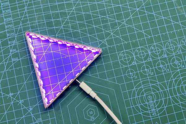
So this is the Nanoleaf 2.0 which is a DIY version of the famous Nanoleaf RGB Triangular lighting setup.
The goal here was to Recreate a Nanoleaf-like device with minimal spec and low cost, one that has all the basic RGB Glowing features and can be made easily.
To accomplish this feat, I prepared this setup completely from PCBs that were provided by PCBWAY.
This Instructables is gonna be about the whole built process of this economic version of Nanoleaf so let’s get started!
Supplies
Following were things required to make this project-
- Custom PCBs
- WS2812B LEDs
- Attiny85 SOIC8
- SMD Button
- USB Micro Port vertical
- 100nf Cap
- 5V Power Source
- Arduino Nano (for flashing Attiny85)
If you want to purchase this Nanoleaf, checkout its tindie link- https://www.tindie.com/products/maepa/nanoleaf-dumb-edition/
Step 1: Prologue
Nanoleaf available on market costs a lot, so I planned this alternate version which doesn’t have any fancy connectivity options like BT or Wifi, I added a button to change the color of LEDs.
This Setup is powered by a USB Port that takes 5V Inputs to power each LED and Attiny85.
I already made a V1 of this setup that you guys can check out from the below link.
https://www.instructables.com/PCB-NANOLEAFHEXALEAF/
In that version, I used 6 LEDs and a THT version of Attiny85.
This edition is similar to the previous one in layout, the only difference is the Attiny85 Package is now SOIC8 instead of DIP8, there are a total of 8 pixels in this board now and the overall length has been shortened to make this setup more compact.
Also, I’ve added a vertical Micro USB Port in this project so we can easily connect a charger to this setup in a nice and tidy way.
Step 2: PCB Design and Schematic
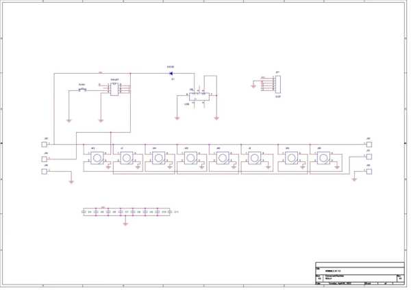
8 WS2812B LEDs are connected in parallel, Dout of First LED is connected to Din of Second LED, Second’s LED Dout is connected with third LED’s Din and this goes on up to 8th LED.
8th LED Dout is connected with a CON1 Pad that will connect with other boards and this sequence will continue on the second PCB as well.
We can add as many PCBs that we like and make different GONS from this setup.
Like previously I made a Dodecgon by preparing a similar setup, We are already preparing Trigon but we can make Tetragon, Pentagon, Hexagon, Heptagon, Octagon, etc.
We just have to use multiple Boards and connect them at a certain angle which is the internal angle between two sides of any gon you’re preparing.
Attiny85 is being used to control the addressable LEDs with an SMD Button.
I prepared its PCB and then send it to PCBWAY for samples.
Step 3: PCB Assembly
PCB Assembly of this project contains the following steps that also include testing the board before adding componenets on the bottom side.
- Solder paste Dispensing
- Pick & Place Process
- Hotplate reflow process
- Checking If the LEDs are working
- Adding Attiny85, Switch, and USB Port
Step 4: SOLDER PASTE DISPENSING
Now the first step is to add solder paste to each component pad one by one.
To Apply solder paste, I’m using a Solderpaste Dispensing Needle with a Wide syringe, and the solder paste I’m using is a regular solder paste consisting of 63% Tin and37% Lead.
Step 5: PCBWAY
I received the PCBs in a week which was fast.
I choose White Soldermask for this project with a Black silkscreen and the overall quality of the PCBs was just awesome.
I have Been using their service for a while and I have to say, it’s pretty decent for getting started.
Checkout PCBWAY from here- https://www.pcbway.com/
Step 6: Pick & Place Process
After applying Solderpaste we move on to the next step which is to add components to their assigned location.
Also, because we are preparing a Trigon setup, we need to make two more boards.
Step 7: Hotplate Reflow
After the “Pick & Place Process”, I carefully lifted the whole circuit board and place it on my DIY SMT Hotplate.
the hotplate heats the PCB from below up to the solder paste melting temp, as soon as the PCB reaches that temp, solder paste melts and all the components get soldered to their pads, we lift the PCB and then place it on a cooler surface for a little bit, to cool down the heat of PCB.
Step 8: Testing LEDs
To check if the LEDs are soldered properly or not, we need to check each board and for that, I used an Arduino nano board connected with three jumper wires that connect VCC GND and Din of LED Board with 5V GND and D3 of Arduino nano.
I used Adafruit’s Neopixel Test sketch to check if the LED was working.
#include <Adafruit_NeoPixel.h>
#ifdef __AVR__
  #include <avr/power.h>
#endif

#define PIN 3

// Parameter 1 = number of pixels in strip
// Parameter 2 = Arduino pin number (most are valid)
// Parameter 3 = pixel type flags, add together as needed:
//   NEO_KHZ800  800 KHz bitstream (most NeoPixel products w/WS2812 LEDs)
//   NEO_KHZ400  400 KHz (classic 'v1' (not v2) FLORA pixels, WS2811 drivers)
//   NEO_GRB     Pixels are wired for GRB bitstream (most NeoPixel products)
//   NEO_RGB     Pixels are wired for RGB bitstream (v1 FLORA pixels, not v2)
//   NEO_RGBW    Pixels are wired for RGBW bitstream (NeoPixel RGBW products)
Adafruit_NeoPixel strip = Adafruit_NeoPixel(8, PIN, NEO_GRB + NEO_KHZ800);

// IMPORTANT: To reduce NeoPixel burnout risk, add 1000 uF capacitor across
// pixel power leads, add 300 - 500 Ohm resistor on first pixel's data input
// and minimize distance between Arduino and first pixel.  Avoid connecting
// on a live circuit...if you must, connect GND first.

void setup() {
  // This is for Trinket 5V 16MHz, you can remove these three lines if you are not using a Trinket
  #if defined (__AVR_ATtiny85__)
    if (F_CPU == 16000000) clock_prescale_set(clock_div_1);
  #endif
  // End of trinket special code


  strip.begin();
  strip.show(); // Initialize all pixels to 'off'
}

void loop() {
  // Some example procedures showing how to display to the pixels:
  colorWipe(strip.Color(255, 0, 0), 50); // Red
  colorWipe(strip.Color(0, 255, 0), 50); // Green
  colorWipe(strip.Color(0, 0, 255), 50); // Blue
//colorWipe(strip.Color(0, 0, 0, 255), 50); // White RGBW
  // Send a theater pixel chase in...
  theaterChase(strip.Color(127, 127, 127), 50); // White
  theaterChase(strip.Color(127, 0, 0), 50); // Red
  theaterChase(strip.Color(0, 0, 127), 50); // Blue

  rainbow(20);
  rainbowCycle(20);
  theaterChaseRainbow(50);
}

// Fill the dots one after the other with a color
void colorWipe(uint32_t c, uint8_t wait) {
  for(uint16_t i=0; i<strip.numPixels(); i++) {
    strip.setPixelColor(i, c);
    strip.show();
    delay(wait);
  }
}

void rainbow(uint8_t wait) {
  uint16_t i, j;

  for(j=0; j<256; j++) {
    for(i=0; i<strip.numPixels(); i++) {
      strip.setPixelColor(i, Wheel((i+j) & 255));
    }
    strip.show();
    delay(wait);
  }
}

// Slightly different, this makes the rainbow equally distributed throughout
void rainbowCycle(uint8_t wait) {
  uint16_t i, j;

  for(j=0; j<256*5; j++) { // 5 cycles of all colors on wheel
    for(i=0; i< strip.numPixels(); i++) {
      strip.setPixelColor(i, Wheel(((i * 256 / strip.numPixels()) + j) & 255));
    }
    strip.show();
    delay(wait);
  }
}

//Theatre-style crawling lights.
void theaterChase(uint32_t c, uint8_t wait) {
  for (int j=0; j<10; j++) {  //do 10 cycles of chasing
    for (int q=0; q < 3; q++) {
      for (uint16_t i=0; i < strip.numPixels(); i=i+3) {
        strip.setPixelColor(i+q, c);    //turn every third pixel on
      }
      strip.show();

      delay(wait);

      for (uint16_t i=0; i < strip.numPixels(); i=i+3) {
        strip.setPixelColor(i+q, 0);        //turn every third pixel off
      }
    }
  }
}

//Theatre-style crawling lights with rainbow effect
void theaterChaseRainbow(uint8_t wait) {
  for (int j=0; j < 256; j++) {     // cycle all 256 colors in the wheel
    for (int q=0; q < 3; q++) {
      for (uint16_t i=0; i < strip.numPixels(); i=i+3) {
        strip.setPixelColor(i+q, Wheel( (i+j) % 255));    //turn every third pixel on
      }
      strip.show();

      delay(wait);

      for (uint16_t i=0; i < strip.numPixels(); i=i+3) {
        strip.setPixelColor(i+q, 0);        //turn every third pixel off
      }
    }
  }
}

// Input a value 0 to 255 to get a color value.
// The colours are a transition r - g - b - back to r.
uint32_t Wheel(byte WheelPos) {
  WheelPos = 255 - WheelPos;
  if(WheelPos < 85) {
    return strip.Color(255 - WheelPos * 3, 0, WheelPos * 3);
  }
  if(WheelPos < 170) {
    WheelPos -= 85;
    return strip.Color(0, WheelPos * 3, 255 - WheelPos * 3);
  }
  WheelPos -= 170;
  return strip.Color(WheelPos * 3, 255 - WheelPos * 3, 0);
}
After making sure that everything was working properly, we move on to the next and final step of PCB Assembly which was Adding Attiny85 and other stuff to the master board.
Step 9: Adding Attiny85 and Other Things to Main Board
From these three PCBs, we need to add one Attiny85 to any of these boards so that board will become the main PCB, the other two will be the LED board that extends the number of LEDs.
After adding Attiny85 along with SMD Button Switch and USB port to the main PCB, we move on to the next step which is to Flash the Attiny85 with the main sketch.
Step 10: Attiny85 Programming
As for the Flashing Process, we cannot directly program ATTINY85 through any USB, I mean there’s a method for programming the Attiny straight from the USB port but I’m not doing that.
Instead, I’ll be using the ISP flashing method which will utilize the SPI Pins of attiny85 to burn the bootloader in it and then Flash.
I already made an Attiny Programmer that uses an Arduino nano to burn bootloader and flash code into any Attiny Device.
On this Attiny Programmer PCB, there’s a CON6 Port that is connected to SPI Pins of Arduino Nano, I’ve added the same port on the Nanoleaf PCB so for programming this Board all I need to do was to place the Nanoleaf onto the CON6 Port.
Getting Attiny85 Core Installed on Arduino IDE
Before starting the Flashing process, we first need to download and install the Attiny85 Core files in Arduino IDE.
https://github.com/SpenceKonde/ATTinyCore
- File->Preferences on a PC, or Arduino->Preferences on a Mac, enter the above URL in “Additional Boards Manager URLs
- Tools -> Boards -> Boards Manager… *If using 1.6.6, close boards manager and re-open it (see below)
- Select “ATTinyCore by Spence Konde” and click “Install”.
AVRs chips usually come blank, they need to be set up to be Arduino IDE compatible but to do that you need an AVR programmer do to that, for example, a USBASP.
Fun Fact, you could make your own AVR Programer with an Arduino Uno or a Nano board in a very easy step.
- Connect your Arduino board with a COM port and select the following sketch
- Example>ArduinoISP upload this sketch onto your board
- After uploading, go to the tools menu and choose the Arduino as ISP option in the programmer section.
- Now for flashing Attiny85, we can select the Attiny85 in the Board section.
The programming process uses VCC, GND, and four data pins. Three pins connect MISO, MOSI, and SCK between the programming micro and the target micro, and the fourth pin from the programming micro goes to the reset pin of the target.
Wire the Attiny85 with Arduino in the above way. (also right after uploading ISP Sketch to your Arduino, do not forget to add a 10uf Cap between Reset and GND pins of your Arduino board)Instead of using an Arduino UNO and a breadboard for this job, I will use my DIY Attiny Programmer which I made for flashing the Attiny or Atmega MCUs.
which you can check out from here-
https://www.instructables.com/Multiple-ATtiny8513A…
- connect the Board to the Arduino as ISP Setup in the above wiring config
- choose the right port, right programmer (Arduino as ISP), and hit Burn Bootloader
- wait for a few seconds, and you will get done burning the bootloader message.
- Now Open the sketch that you want to upload to this AttinyGo to the Sketch menu and select Upload using the programmer.
- and your Sketch will get uploaded onto the attiny85.
Step 11: Main Code
Here’s the main code-
#include <Adafruit_NeoPixel.h>

#define BUTTON_PIN   4
#define PIXEL_PIN   0   // Digital IO pin connected to the NeoPixels.

#define PIXEL_COUNT 24

Adafruit_NeoPixel strip = Adafruit_NeoPixel(PIXEL_COUNT, PIXEL_PIN, NEO_GRB + NEO_KHZ800);

bool oldState = HIGH;
int showType = 0;

void setup() {
  pinMode(BUTTON_PIN, INPUT_PULLUP);
  strip.begin();
  strip.show(); // Initialize all pixels to 'off'
}

void loop() {
  // Get current button state.
  bool newState = digitalRead(BUTTON_PIN);

  // Check if state changed from high to low (button press).
  if (newState == LOW && oldState == HIGH) {
    // Short delay to debounce button.
    delay(20);
    // Check if button is still low after debounce.
    newState = digitalRead(BUTTON_PIN);
    if (newState == LOW) {
      showType++;
      if (showType > 14)
        showType=0;
      startShow(showType);
    }
  }

  // Set the last button state to the old state.
  oldState = newState;
}


void startShow(int i) {
  switch(i){
    case 0: colorWipe(strip.Color(0, 0, 0), 50);    // Black/off
            break;
    case 1: colorWipe(strip.Color(255, 0, 0), 50);  // Red
            break;
    case 2: colorWipe(strip.Color(0, 255, 0), 50);  // Green
            break;
    case 3: colorWipe(strip.Color(0, 0, 255), 50);  // Blue
            break;
    case 4: colorWipe(strip.Color(100, 0, 255), 50);  // purp
            break;
    case 5: colorWipe(strip.Color(200, 0, 255), 50);  // lite purp
            break;
    case 6: colorWipe(strip.Color(255, 0, 100), 50);  // pink
            break;
    case 7: colorWipe(strip.Color(255, 255, 0), 50);  // yellown
            break;
    case 8: colorWipe(strip.Color(255, 110, 20), 50);  // orange
            break;
    case 9: colorWipe(strip.Color(255, 100, 100), 50);  // Rorange
            break;
    case 10: colorWipe(strip.Color(255, 180, 40), 50);  // lite orange
            break;
    case 11: colorWipe(strip.Color(0, 255, 255), 50);  // LIGHT Blue
            break;
    case 12: colorWipe(strip.Color(0, 255, 100), 50); //greenish blue
            break;
    case 13: colorWipe(strip.Color(150, 255, 0), 50);  //greenish red
            break;
    case 14: colorWipe(strip.Color(255, 255, 255), 50);  // white
            break;
  }
}


void colorWipe(uint32_t c, uint8_t wait) {
  for(uint16_t i=0; i<strip.numPixels(); i++) {
    strip.setPixelColor(i, c);
    strip.show();
    delay(wait);
  }
}
Step 12: PCB Working
We power the main board by using a 5V smartphone charger, we then connect the USB and press the push button.
This will start the Color wipe sequence, there are a total of 14 different color options available but you can decrease or increase the number of colors by changing the code a little bit.
Step 13: Final Assembly
The Trigon shape consists of three sides which have an internal angle of 60°.
Here’s how I did the final assembly, I use fiber tape to hold two PCBs together and then connected the third one, and then use tape to bind all PCBs together to make an equilateral triangle.
After preparing the main shape, I soldered the VCC Pads of all three sides together along with Din Dout Pads and Gnd Pads.
Step 14: Result
here’s the result of this built!
This is it for today folks, thanks for reading this article.
Thanks PCBWAY for supporting this project, you guys can check them out if you need great PCB and Stencil service for less cost and great quality.
And I’ll be back with a new project pretty soon!
Source: Nanoleaf 2.0
- How is the Nanoleaf 2.0 powered?
The setup is powered by a USB port that takes 5V inputs. - Can I connect multiple boards together?
Yes, you can add as many PCBs as needed by connecting the Dout of one board to the Din of the next. - What components are required to make this project?
You need custom PCBs, WS2812B LEDs, Attiny85 SOIC, SMD Button, USB Micro Port vertical, 100nf Cap, 5V Power Source, and an Arduino Nano. - Does this version have Bluetooth or WiFi connectivity?
No, this alternate version does not have fancy connectivity options like BT or Wifi. - How do I test if the LEDs are soldered properly?
Use an Arduino nano connected with jumper wires to VCC, GND, and Din of the LED Board, then run the Adafruit Neopixel Test sketch. - What is the best way to flash the Attiny85 chip?
The article recommends using the ISP flashing method with an Arduino Nano configured as an ISP programmer. - How many color options are available in the main code?
There are a total of 14 different color options available in the provided code. - How are the three PCBs assembled to form a triangle?
Fiber tape is used to hold two PCBs together at a 60-degree angle, then the third is added and all are bound together before soldering pads. - What type of LEDs are used in this project?
The project uses 8 WS2812B addressable LEDs per board. - Where can I purchase the PCBs for this project?
The author prepared the PCBs through PCBWAY, which they recommend for samples.