This project is an Arduino-powered infrared touchscreen / coffee-table interface that I’ve been using to control various music and graphics applications on my computer. This is an old project that I’ve recently had time to go back and document/fix up; this project is a little more special to me than most because it was my first Arduino/electronics project, and while I was doing research for it I ended up on Instructables for the very first time. I’ve been using this controller primarily to drive music and graphics applications running in MaxMSP.
The touchscreen uses infrared (IR) sensing to detect fingers and other objects on the screen. An IR laser at each corner shines IR light across the surface of the screen. When a finger or other object touches the surface, it causes the IR light to scatter in many directions. Some of this light is directed down into the screen, towards an array of 64 IR sensors. By scanning through the sensors, you can determine the x and y position of the touch event(s) and use this to control a variety of apps.
An array of 64 LEDs underneath the display provides visual feedback for the interface via rear projection. The LED array operates completely independently from the sensor array – this means the LEDs may be used in more ways that just displaying the current touch positions.
This interface is a controller, it does not run apps that are stored in its memory (though that is possible). Instead, it connects to a computer via USB and sends a series of touch messages to control applications running on the computer (similar to how a computer keyboard sends keystrokes to a computer). The computer processes the input data and determines the configuration of the output display, then it sends a series of LED messages back to the interface (similar to how the computer drives an LCD display). This way, the controller is very simple and does not need to handle any processing outside of the basic tasks of getting the states of its inputs (IR sensors) and setting the states of its outputs (LEDs); the computer is doing all the heavy lifting in this scenario.
As I said before, this device relies on IR sensing as input information, I found out by accident that it does some cool stuff when you put it outside while the intensity of sunlight is changing rapidly (sunrise/sunset). I had some fun trying to find interesting ways of transforming seemingly random noise from the inputs into sound/lights:
Although the project was done a while ago, I’ve taken it apart recently to refinish the wood and fix a few things that were bugging me. I’ve still written this Instructable as if I was building it from scratch, but it will be obvious at times that this is, in fact, a finished project.
Hot tip: the schematic and firmware used in this project is a modified version of the Arduinome project, which is a modified version of the Monome project. If you run into problems during any stage of this project, you might find what you are looking for in one of those forums.
Safety note: this project uses laser diodes strong enough to permanently damage your eyes (or the eyes of those around you), do not use lasers if you don’t know how to handle them properly.
PARTS LIST:
Various Sources
(x4) 25 milliwatt 780nm laser diodes with 89 degree line lens Aixis AIX-780-25-8 – really important note here, even though these lasers are labelled “3.2V,” they are actually 5V, this took me a really long time to figure out.
(x1) rosco black projection screen (a ~2′ by 2′ piece at least) Rose Brand
(x1) Arduino Uno (I used a Duemilanova, but an Uno should work too) Sparkfun DEV-11021
(x1) 20″x20″ phenolic sheet (for installing LEDs and IR sensors)
(x1) wood 2×4 (for enclosure- I used some redwood that was laying around
(x1) 1mm aluminum sheet (for light-tight partitions underneath screens) enough to make 14 20″ x 2.5″ pieces – I used black anodized aluminum, but regular un-anodized aluminum should work fine too.
(x1) 20″x20″x¼” glass pane
Digikey
(x64) 800nm IR phototransistors Digikey 511-1357-ND
(x64) white wide angle LEDs Digikey C535A-WJN-CS0V0231-ND – I found that the quality control on these LEDs is not so great, and they each turned out to be slightly different shades of white. I thought the effect actually looked pretty cool, but if that’s not what you’re into, I’d try to find some other wide angle LEDs.
(x1) MAX7219 LED driver Digikey MAX7219CNG -ND
(x1) 24 pin socket Digikey 3M5466-ND
(x1) 10uf capacitor Digikey P828-ND
(x1) 0.1uf capacitor Digikey 490-5401-ND
(x1) 74HC595 shift register Digikey 296-1600-5-ND
(x1) 16 pin socket Digikey A100206-ND
(x10) 10kOhm 1/4 watt resistors Digikey CF14JT10K0CT-ND
(x1) 1/4 watt 7219 resistor (value determined here depending on your LEDs)
Amazon
(x2) usb cable male type A to male type b Amazon
(x1) usb adapter female type a to female type b Amazon
(x1) perfboard with copper Amazon
(x1) polycrylic clear coat Amazon
(x1) silicon adhesive Amazon
(x1) black electrical tape Amazon
Jameco
(x1) 16 pin ribbon cable Jameco 643532
(x1) 16 pin crimp socket Jameco 1578111 (I didn’t actually use this but I wish I had)
(x5) male header pins Jameco 103393
(x1) 22 gauge solid core wire Jameco 36792
Tools:
screwdriver
hot glue gun
drill
table saw
wood mill/router
aluminum mill
aluminum sheet cutter
bandsaw
soldering iron
infrared/nightvision camera (optional, but useful)
Step 1: LLP (Laser Light Plane)
Infrared (IR) multitouch is an inexpensive alternative to the capacitive multitouch found in smartphones and tablets. There are a few popular techniques for building an IR multitouch system, all of which are outlined very nicely at the nuigroup wiki.
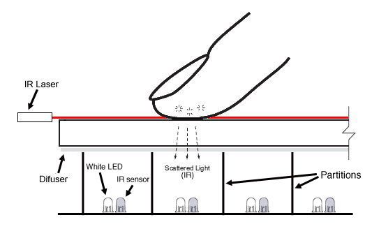
I used a technique called Laser Light Plane (LLP) for my touchscreen; the diagram above gives an overview of how it works. Several lasers positioned on top of the screen create a very thin layer or infrared (IR) light that completely covers the screen’s surface. When a finger touches the screen, it breaks this plane of light and scatters some of the IR light into the screen. I partitioned the underside of the screen with pieces of aluminum sheet and placed one IR sensor in each partition. By measuring each of the sensors, you can determine the x and y coordinates of the touch event. I also added a white LED to each partition, so that the screen could be used as a projection surface. The diffuser material on the bottom of the screen (light grey) helps the LED more evenly distribute light across the surface of the screen.
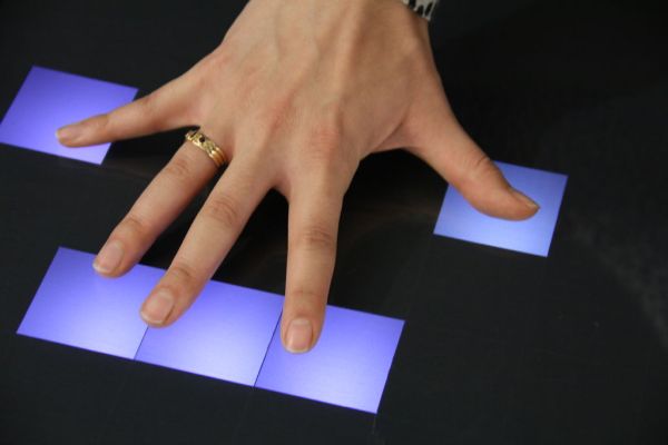
This is what LLP looks like with red lasers, IR will work the same, but it is not visible to the human eye:
I won’t get into the specifics of every IR multitouch technique here (again, check nuigroup for that info), but I’ll say a few things about why I chose LLP:
zero force – no downward pressure on the screen is necessary to register a touch.
glass – I wanted to use glass as my screen surface (looks/feels nicer, less scratch prone than acrylic), but some IR multitouch methods (total internal reflection) require acrylic.
thin – many IR multitouch techniques us a camera to do the finger tracking, this means that the camera must be positioned so that it has an unobstructed view of the entire screen. Usually this means making the enclosure of the multitouch surface very deep so that the camera is sufficiently far away. By contrast, my method of using an array with LLP can be scaled down to thicknesses of less than an inch.
scalable – the unit piece of this touchscreen – the cell containing one LED and one IR sensor – can be repeated many times to make larger or denser arrays.
Some downsides to LLP:
– anything that breaks the surface of the screen will trigger the sensors – sleeves, elbows… sometimes that is annoying. It could be a good thing though, you can use regular objects to trigger the touch.
– the downfall of all IR touchscreens is that they are sensitive to IR light. This screen only works at night or in a room with no windows, and the light in the room can only be fluorescent – no incandescent bulbs.
Another good resource for LLP information is at the nuigroup llp page.
Image source: parts of the above image are taken from nuigroup
Step 2: Schematic
My schematic is a modified version of the Arduinome schematic found here. A little info about why I based this off Arduinome… When I was first researching online for ideas I knew I wanted to make some kind of LED array / coffee table / control surface
Searching for more Arduino / grid controllers, I found monome and Arduinome. It was (and still is) the best solution for this type of project because once you build the interface, you have access to all the MaxMSP applications that people post on the monome site – and there’s some really creative and amazing apps there – so you’re getting a lot of value out of the work you put in. Because these apps are written in MaxMSP, they’re open source, so if you want to, you can edit them and learn more about how they work. Aaand if you ever end up writing your own applications, you can post them and see what other people do with them, which is always kind of fun.
The most notable modification I’ve made form the original Arduinome schematic is that I’ve replaced all the buttons, and their corresponding diodes, with IR phototransistors (since the transistors have an inherent polarity, diodes are not necessary).
I’ve also replaced the 74HC164 with a 74HC595. On paper these chips are not too different, but I found that one of the pins on the 164 was dropping in voltage slightly in the Arduinome schematic. This is not a huge deal when you’re controlling buttons because they are 2-state devices, but it was causing one row of my sensors to be significantly less sensitive than the rest. I tried to troubleshoot this and could not find a way, so I replaced it with the 595 and had much better results. I also simplified the circuit by removing the 74hc165 and using 8 pins on the Arduino instead. I had to change the Arduinome firmware to account for these changes, you’ll find that in a later step.
For more detail: Make A Multitouch Music Controller Using Arduino