A while ago I made a large 20 sided Die. Numerous people wanted me to build them one and since the most difficult part of the project was getting the cutting angles just right, I decided to make another which would allow for more accurate assembly. This time 3D printed instead of plywood and glue. I also added some much needed flair!
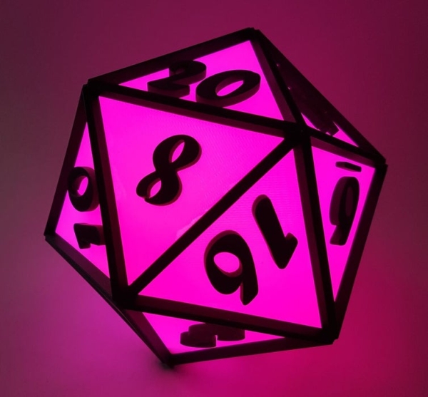
There are 2 varieties presented here, the LED lamp version and a playable large scale DIE. I have included a drawing step so that you can easily recreate the parts to scale it as you wish.
This covers making the LED conversation piece and since less steps are required for the playable one, that one too.
Step 1: How to Draw the Icosahedron D20 Face
Go to step 3 if you just want the files…
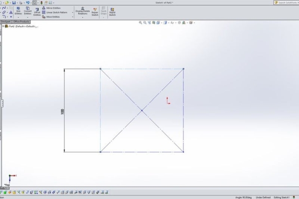
I used 3D modelling software to create this. The procedure is as follows.
- Select a starting plane.
- Away from the sketch origin draw a construction rectangle, make the sides equal then define a side length(I used 100mm)
- Pick any side and mark the centre point of the side.
- Use this as a centre point of an arc. Set the arc radius at either opposite corner then draw the ark down to the starting line away from the original square.
- From the square corner draw a construction line to the arc end point then up and then over to the arc radius point.
- You should now have a square joined to a smaller rectangle. The large rectangle created in this specific configuration is called a golden rectangle. From the mid point of the short side of the Golden Rectangle draw a line across to the other short side and mark the mid point of this line. Set this mid point as a coincident to the origin of your drawing.
- Now repeat this procedure for each remaining plane and make sure the drawings are perpendicular to the the long side of the previous rectangle.
- Next select the same square edge on all 3 drawings the was used for dimension and make the property equal. This way you only have to change 1 dimension to change the size of all 3.
- Looking on the sketches in an isometric view, create a new plane using the 2 points along the short side of one Golden Rectangle and the highest closest point to the first 2.
- Use this as a sketch plane and draw a triangle using the 3 points that were used to define the plane.
- Using the loft feature select this triangle sketch and the origin point to create a 3 side pyramid
- Now use the same sketch plane and make an oversized rectangle then set the offset to the desired thickness (6mm used here) and cut the rest away.
- Decorate as desired! I used the included font in my cad program set to size 140.
Step 2: Download and Print
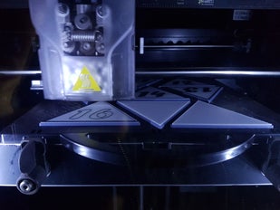
I can only get 9 of the panels to fit on each model base panel so there is going to have to be 3 jobs for this.
In my case it works out to about 9 hours total print time with solid shapes.
I wanted to make the surface of the panels translucent and the letters solid colour. This surface layer is 1mm thick with translates to 4 layers of .25mm thick on my machine
I chose to use ABS in both natural and black for printing
My software allows the addition of a print pause which allows me to change the material colour from natural to black in this case.
Layer 13 on my model plate is the first layer that will print above the solid background. The pause is before the layer begins so it was set here.
If you are wanting to make the lighted version, do not print panel 1 here. There is more on this later.
Step 3: Assembly
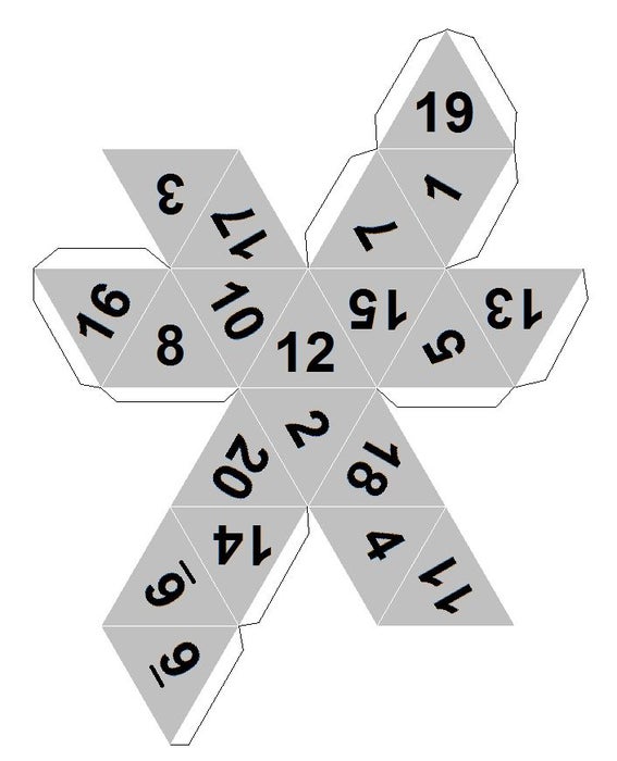
There is much debate on the proper 20 sided Die numbering outside of the opposite sides added together get you 21.
I Chose this one! I know I will probably get some comments here…
Following this I wanted to have a critical hit always showing so I made the 1 panel which should orient to the bottom as the base access port.
Now, since the panels are about 6mm thick they should self align when they are clamped together.
I started at 20 and worked outward from there. The first panel is added and then carefully aligned along the back side. It is clamped together along the black edging. I had some small spring clamps but found that ordinary binder clips worked great for this.
From the back side then add solvent cement to the seam and leave clamped for the recommended amount of time.
When 2 adjacent panels are joined there is an odd grove created, I was going to fill this but found that I liked the texture that it created.
Continue with this until you have only the “1” panel left, do not glue this one in place if you are making the light.
Step 4: Panel 1
If you are assembling the non lighted version, You should be done.
I chose to make where panel 1 normally would be into a base that will cover the access and support the electronics inside.
Initially this was to be secured and hidden but this would have created a whole set of other problems with durability
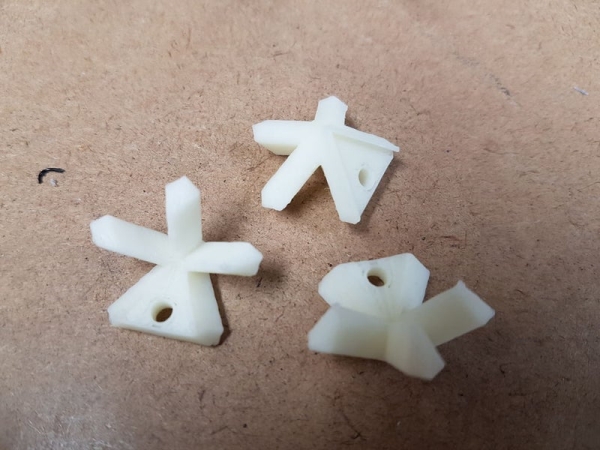
I made the bottom cover with 3 screw holder to secure it. Therefore I had to make corner structures for this.
Right here is where I made a critical mistake. I measured and drew the separate parts then printed without first modelling it or testing the fit in an assembly.
The screw holes for the corner securing points did not line up!
I had to drill 3 new screw insert holes then modify one corner with a hot iron to correct this since I glued them in place.
The files here have been corrected
The base is held in place with 4-40 screws and there is only 1 button.
Step 5: The Illumination
I made an internal RGBW lamp from parts found here!
This is driven with an Arduino using a slightly modified code from the NeoPixel library.
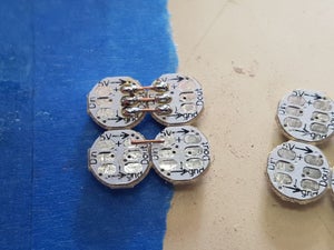
The panels are a 6 sided free form cube consisting of 4 lights on each face.
I used small copper strands to connect the tiny boards together.
All of the lights are connected in series with long tails for attaching to the microcontroller.
The 2 long strips are folded in groups of 4 to make a u shape then the 2 u shapes are interlocked to make a cube.
Using hot glue, which is the worst possible type of adhesive to use here, I tacked the corners of the cube together.
The leads were marked for proper connection.
The cube is then glued to the pillar on the base panel as shown.
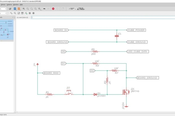
The circuit is fairly basic, The button controls all.
Step 6: Operation and Electrics
I made a minor code modification to the original NeoPixel strandtest , I have included it here called d20.ino.
To begin the button is pressed and held, this will supply power to the microcontroller through a MOSFET. Contrary to what the schematic says, I used an IRF9530N since I had many of these in my parts bin.
The switch input is wired in parallel with the microcontroller digital port D2.
Once the program starts the cube will light up, the microcontroller will take over and switch the board power on through the MOSFET via pin D2.
Subsequent button presses will scroll through the NeoPixel test functions.Holding the button down will fast scroll through the light functions.
The final switch press will turn pin D2 off and upon release of the button, the strip will go dark and the power to the microcontroller is shut off.
The battery carrier is held in place with 2 side carpet tape and the board is hot glued to the top of the battery carrier.
I am going to be changing the MOSFET to a small relay in the near future since there is enough current to slightly light the power LED on the NANO board.
Source: Multicolour LED Icosahedron