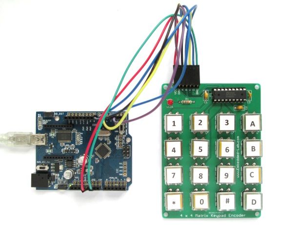
Matrix keypads are an excellent way of providing user input data into microcontroller-based systems. Keypads find applications in remote controls, standalone data-loggers, security systems, door entry systems, calculators, microwave ovens, etc. They are usually implemented as pushbutton switches arranged in a row and column matrix format to reduce the number of I/O connections. For example, a 16-switch keypad is arranged in a 4 X 4 matrix format requiring 8 I/O connections. A pressed key is detected and identified by scanning the keypad to look for a short circuit condition between a row and a column wire. The keypad scanning can be done either by polling or by means of an interrupt routine. In the polling approach, the scanning process is repeated in a continuous loop, which results in waste of CPU time. The interrupt-approach is more efficient and it notifies the processor when there is a keystroke. Another approach of interfacing a keypad to the microcontroller is by using a dedicated keypad encoder IC, which further reduces the I/O connections and makes the interface much simpler. In this project, we are building a simplified 16-switch keypad using the MM74C922 encoder chip, which converts a key switch closure to a 4-bit nibble output.
Theory
The MM74C922 chip is available in 18-pin DIP and 20-pin SOIC packages. This project uses the DIP version, which has the pin configuration as shown below.
The MM74C922 encoder implements all the logic necessary to interface a 16-key switch matrix to a digital system. The encoder chip continuously scans the keypad waiting for a key press. When a switch is pressed, it provides a 4-bit nibble corresponding to the pressed switch at its output pins D, B, C, and A (14-17). The chip has a built-in debounce circuit, which requires a single external capacitor to be connected to Keybounce Mask pin (6) to operate. The value of the capacitor depends on the required debounce time. When a valid key press is detected and the key bounce circuit times out, the encoded data is latched to the output port and the Data Available (DAV) pin (11) goes high. The DAV pin falls back low when the pressed key is released. The DAV output can be thus used as an interrupt signal for the processor when there is a keystroke. The latched output remains active at pins A through D even after the key is lifted. New data will be available at a new keystroke. The chip also has the two-key rollover feature, which disregards any second key press during an active keystroke. The keypad scanning rate is also configurable through an external capacitor connected to the Oscillator pin (5). The graphs below show the dependency of debounce time and scan rate on the respective capacitor values.
For more detail: MM74C922N-based encoded matrix keypad

