Summary of Midi Light Show using Arduino
This article outlines a project to build an Arduino-based MIDI light system where specific LED colors correspond to musical notes. The setup connects an Arduino with a Midi Shield to an RGB LED, using resistors to manage voltage for consistent brightness across different colors. The system reads three-byte MIDI data (note on/off, pitch, volume) via serial communication to trigger the lights, offering a simple yet expandable foundation for interactive music visualization.
Parts used in the MIDI Light Show:
- 1 Arduino (Freeduino v 1.22 or compatible)
- 1 Midi Shield (DF Robot Midi Shield)
- 1 RGB LED (4 pins)
- 1 MIDI Cable (USB to MIDI optional)
- 2 1kΩ resistors
- 1 560Ω resistor
- Wires (Red, Green, Blue, Black)
- Breadboard
- 4 Extended Headers (Optional)
For a class, my teammate and I decided to develop a MIDI based system that has a responsive light for each note played. For example, if you plug our little setup to a keyboard, pending on which note you press, you’ll get a specific color. You’ll need a list of several items, but the reward is quite nice! Plus, there are a lot of possible improvements and developments from the original idea, so please take the liberty to expand on this concept once you’ve put everything together.
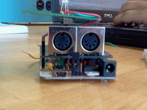
Step 2: Putting It All Together
The main format of this schematic is that each pin of the LED is connected to a different pin on the Midi Shield. note the lower voltage for the red leg of our LED. The cathode goes to ground. The midi shield connects on top of the Arduino, which is why extended headers are necessary for the function of our lights. This is an extremely simple and straightforward build, but it provides a lot of room for expansion as well.
Step 3: Midi Concepts…
To program with Midi, you must understand a few key concepts that determine how the information is read.
Midi sends information with 3 bytes of information at a baud rate of 31250. The first byte determines whether a note is turned on, the next byte determines what pitch is played, and the third byte determines the volume of the note. It is important to note the order of the information as if you don’t set the code to read in this order for only 3 bytes, funny things start happening. Trust us.

Consider the following code:
//reads the serial port to see if there is any incoming information
boolean check_midi()
{
   while (Serial.available() >= 3)//when three bytes available
   {
     if (Serial.available())
     {
       digitalWrite(3,HIGH);
       location_byte = Serial.read();//read first byte
       in_note = Serial.read();//read next byte
       in_volume = Serial.read();//read final byte
       return true;
     }
   }
}
What you’ll need…
Step 1 — Materials Needed:
1 Arduino- The Arduiono used for this project was a Freeduino v 1.22. This did not come pre-assembled, Other boards can be used, as long as the pins are able to line up with those used on the midi shield
1 Midi Shield- DF Robot Midi Shield (http://www.dfrobot.com/index.php?route=product/product&product_id=526). This Midi Shield did NOT come with extended headers, so we needed to replace the pins connecting the shield to the arduino with extended headers. This process requires desoldering and soldering tools, so consider this when choosing your midi shield.
1 LED- RGB LED (4 pins) — Check the information on your LEDs before using them. You can use an LED calculator http://led.linear1.org/1led.wiz to determine the proper resistors needed for your circuit. The Arduino produces 5 volts.
1 MIDI Cable (USB to MIDI is optional, it depends on the instrument used with your midi shield
2 1kΩ resistors (Brown-Black-Red)
1 560Ω resistor (Green-Blue-Brown)
The resistors used depends on the LED. These resistors produced a consistent brightness between all three colors. the 1kΩ resistors were used for the blue and green legs, and the 560Ω resistor was used with the red leg.
Wires — For the simplest experience, choose Red, Green, and Blue wires for the different legs of the LED, and a black wire as the ground.
Breadboard
4 Extended Headers (Optional) Only used if the Midi shield needs to be modified.
For more detail: Midi Light Show using Arduino
- What components are required to build this MIDI light system?
You need an Arduino, a Midi Shield, an RGB LED, three resistors (two 1kΩ and one 560Ω), wires, a breadboard, and optionally extended headers. - How does the MIDI signal structure affect the code?
MIDI sends information in three bytes at 31250 baud rate: note status, pitch, and volume, which must be read in that specific order. - Why are extended headers necessary for this project?
Extended headers are needed if the Midi Shield does not come with them, allowing the shield to connect properly on top of the Arduino. - Can I use any Arduino board for this project?
Yes, other boards can be used as long as their pins align with those used on the Midi Shield. - Which resistor values should be used for the LED legs?
The 1kΩ resistors are used for the blue and green legs, while the 560Ω resistor is used for the red leg to ensure consistent brightness. - Does the project require a USB to MIDI cable?
A USB to MIDI cable is optional depending on the instrument being used with the Midi Shield. - What is the function of the cathode in the LED connection?
The cathode goes to ground, while each pin of the LED connects to a different pin on the Midi Shield. - How can I determine the proper resistors for my circuit?
You can use an LED calculator like led.linear1.org/1led.wiz to find the correct resistors based on your specific LED.