
Summary of Microcontroller Projects: Sonar Water-Level Meter
This article describes a low-cost, wireless sonar-based water-level indicator capable of measuring up to four meters with 5mm accuracy. It addresses the scarcity of fresh water by offering a contactless solution that avoids the rusting issues of mechanical systems and the high cost of commercial ultrasonic meters. The system comprises a transmitter unit using an HC-SR04 sensor and ATmega328P microcontroller, and a receiver unit with an LCD display, both communicating via 433MHz modules.
Parts used in the Wireless Sonar Water-Level Indicator:
- ATmega328P microcontroller (IC1 and IC3)
- Arduino Uno bootloader
- HC-SR04 sonar sensor
- 433MHz transmitter module (TX1)
- 433MHz receiver module (RX1)
- 7805 voltage regulator (IC2 and IC4)
- 4×16 alphanumeric display (LCD1)
- Spiral antenna
- LED2 indicator
- Relay and contactors (optional for pump control)

Three-fourths of the earth is water, out of which 97 per cent is saline (in oceans, seas and groundwater). The remaining 2.5 per cent to 2.75 per cent is fresh water , out of which 1.75 per cent to two per cent is frozen in glaciers, ice and snow. Fresh groundwater and soil moisture constitutes only 0.7 per cent to 0.8 per cent. Less than 0.01 per cent, available as surface water in lakes, swamps and rivers, is available to us as drinking water. It is therefore imperative that systems are in place for managing this precious and scarce resource.
Water-level indicators for water-storage tanks are mostly mechanical contraptions. Steel wires, pulleys and rails get rusted as these are in continuous contact with water and air, resulting in unreliable operation. Contactless sonar-level metres are there but their high cost is a deterrent.
In this article, a sonar contactless, wireless water-level indicator, which can be fabricated for less than Rs. 2500, has been described. It is capable of measuring water levels up to four metres with an accuracy of less than 5mm.

Circuit diagram of the transmitter unit
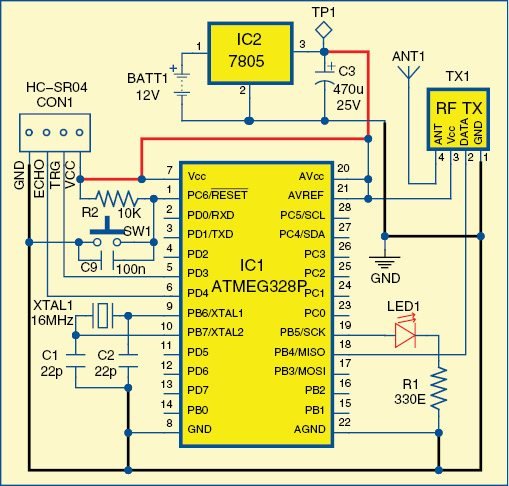
Circuit diagram of the transmitter unit
Circuit and working
The water-level indicator has two units: transmitter unit and receiver unit.  The circuit diagram of the transmitter unit is shown in Fig. 1. It is built around ATmega328P microcontroller (MCU) (IC1) with Arduino Uno bootloader, sonar sensor HC-SR04 connected at CON1, 433MHz transmitter (TX1), voltage regulator 7805 (IC2) and a few other components. a long spiral antenna is used for enhancement of its range.
Attach the contactless sonar sensor at a strategic location on the tank so that it can always get the reflected signal from the water surface. The best place would be at the centre of a circular tank’s lid on top, or at the intersection of the diagonals of a rectangular tank’s top. The calculated tank level will then be transmitted with a coded authorisation to the receiver unit.
An ultrasonic ranging module provides 20mm to 5000mm non-contact measurement facility. Ranging accuracy is 3mm and aperture angle is 15°. Since we are measuring the level in centimetres in the form of an integer, our accuracy level is maximum 5mm. Even a 1cm level change will be seen very clearly, as every second it takes eight readings, which are then averaged out to get better accuracy.
Circuit diagram of the receiver unit is shown in Fig. 2. It is built around ATmega328P MCU (IC3) with Arduino Uno bootloader, voltage regulator 7805 (IC4), 4×16 alphanumeric display (LCD1), 433MHz receiver (RX1) and a few other components. The receiver checks the code word sent by the transmitter unit and displays the tank level on the LCD.
If the transmitter stalls or its power supply gets interrupted, there is no way for the receiver to find out that the incoming signal is no longer valid. To circumvent this problem, a counter has been provided on the right side of the LCD display. If the counter does not move, or it stops, it means that the incoming signal has stalled. Blinking of LED2 connected on pin 19 will stop, too.
Control relay and contactors can be connected on spare pins of ATmega328P, which finally controls the running of the water pump. Since there is no physical contact used in the sensory system, it will be operational without any interruption.

Actual-size PCB pattern of the transmitter unit
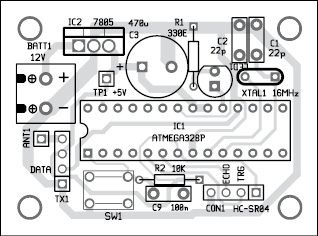
Component layout of the PCB shown in Fig. 3
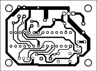
Actual-size PCB pattern of the transmitter unit
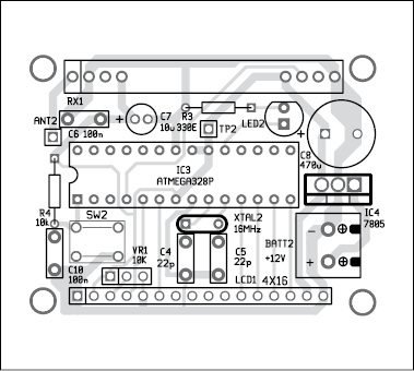
Component layout of the PCB shown in Fig. 5
Download PCB and component layout PDFs: click here
Software
Software comprises one remote_sonar_water_level_transmitter.ino file and one remote_sonar_water_level_receiver.ino file, besides some header files of Arduino. All are packed in the resource directory. Add these libraries to Arduino and upload the two files in the respective transmitter and receiver units.
Download source code: click here
Construction and testing
An actual-size, single-side PCB of the transmitter unit is shown in Fig. 3 and its component layout in Fig. 4. An actual-size, single-side PCB of the receiver unit is shown in Fig. 5 and its component layout in Fig. 6.
After assembling the two units, switch on the power supply of both the units. If the receiver receives the transmitted signal, LED2 will start blinking. The two small digit counters on the right top of the LCD will start changing and the water level (in centimetres) will show on the left-top position. Keep the small spiral antennae in vertical position to have the best radiation.
Somnath Bera is an avid user of open source software. Professionally, he is a thermal power expert and works as additional general manager at NTPC Ltd
Read More Detail :Microcontroller Projects: Sonar Water-Level Meter
- What is the primary advantage of this project over mechanical water-level indicators?
The system uses contactless technology, preventing rust caused by continuous contact with water and air which plagues mechanical contraptions. - Can this device measure water levels up to four meters accurately?
Yes, the device is capable of measuring water levels up to four metres with an accuracy of less than 5mm. - How does the system indicate if the transmitter signal has stalled?
A counter on the right side of the LCD will stop moving, and LED2 connected on pin 19 will stop blinking. - Where is the best location to attach the sonar sensor on a tank?
The best place is at the centre of a circular tank's lid or at the intersection of the diagonals of a rectangular tank's top. - What is the maximum cost to fabricate this water-level indicator?
The system can be fabricated for less than Rs. 2500. - Does the system use physical contact for sensing the water level?
No, since there is no physical contact used in the sensory system, it operates without interruption. - How often does the ultrasonic module take readings to ensure accuracy?
It takes eight readings every second, which are then averaged out to get better accuracy. - Can this system control a water pump automatically?
Yes, control relays and contactors can be connected on spare pins of the ATmega328P to run the water pump. - What software files are required to operate the transmitter and receiver units?
The system requires remote_sonar_water_level_transmitter.ino and remote_sonar_water_level_receiver.ino files along with Arduino header libraries.