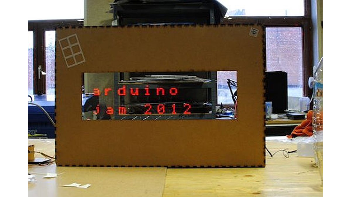
First of all we would like to thank everybody that helped organizing the 2nd edition of Arduino Jam, and especially the Jo3ri, who supplied us with some quite cool goodies and kept us safe during the weekend. (Video will come soon!)

This project is a contribution to the second belgian Arduino Jam (2012) at Timelab, Ghent.
During this edition I teamed up with Jeff to build a mechanical light ticker display. The initial idea was to do something with time lapse and motion control.
The bill of materials is the following
- An Arduino Uno
- A Pololu motor driver carrier (H-Bridge)
- An old inkjet printer rail
- A Raspberry Pi (optional, just to have a nice web interface to input some text)
- Two led matrix displays (Using a MAX72XX driver)
- A copper arm (to carry those led matrices)
- A camera (DSLR) on a tripod that allows you to set shutter speeds longer than 5s
You can find the source code for this project attached in the zip file. The code was adapted to work with Netbeans. Just copy the constants.h and project.cpp contents to a new ino file if you want to build it with the Arduino IDE.
Get your stepper motor up and running
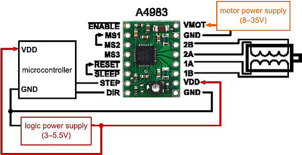
Firstly we did a couple of small tests with the pololu stepper driver. Therefore we wired up the motor according to the schematic here below. We used a bench supply at about 12V as the motor power supply (higher voltages might work even better here).
Driving the motor was then just a matter of
- Driving the ENABLE pin LOW
- Setting the dir pin to LOW or HIGH (depending on the direction you want the motor to turn)
- Sending a LOW (stop) or HIGH (drive) to the STEP pin
The motor was then attached to the rubbers of a rail of an old inkjet printer (see second picture). We had to drill two holes in the metal to attach our stepper properly. After tightening the rubber a bit, everything was working fine.
We also attached a click button at one end of the rail, so the system would be notified when the carry hit the end of the rail. The code foresaw a routine that stopped the motor when this event would occur. We did this by using a polling loop (no interrupt was needed here)
Step 2: Drive the LED matrix displays
After hooking up the display, we ran an example program and saw the LEDs light up nicely. However, there was a small bug in the setup, as for some reason the last line was shifted to the top of the matrix, This caused certain letters to be truncated. We solved this by bitshifting the pattern for each character to the right just once.
After some searching we found a complete character to bit pattern mapping for those LED matrices on the AVR freaks forum.
Now it was just a matter of making some code that was able to map a single character to its corresponding bit pattern. We did this by using a 2D array and casting a given character to it’s corresponding int value (1 – 128) and use this as a first index for the 2D array.
When we had the first display working, we decided to add a second one. The wiring is quite easy here, you can just daisy chain the second starting from the first one. The library that comes with the display is also well written and the code was easily adapted (just duplicate a couple of lines)
Step 3: Building a nice enclosure
Finally we decided to build a nice enclosure to give the project a better look. Jeffrey used the laser cutter to construct a big wooden box with a big opening in the front through which we could see the LED matrix displays.
For the designs he used the maximum size of wood plate for the cutter and boxmaker to generate the typical cutted edges to snap together nicely.
- An Arduino Uno
- A Pololu motor driver carrier (H-Bridge)
- An old inkjet printer rail
- A Raspberry Pi (optional, just to have a nice web interface to input some text)
- Two led matrix displays (Using a MAX72XX driver)
- A copper arm (to carry those led matrices)
- A camera (DSLR) on a tripod that allows you to set shutter speeds longer than 5s
For more detail: Mechanical Led Matrix Display

