Summary of MEASURING ELECTROMAGNETIC FIELDS WITH JUST AN ARDUINO AND A PIECE OF WIRE
This article describes a DIY handheld electromagnetic field (EMF) detector built using an Arduino to identify WiFi slowdowns and TV signal drops. The device connects an antenna to the Arduino's analog input, utilizing a high-impedance ADC sensitive to stray currents. To prevent noise triggering, an adjustable resistor is used, and the unit is housed in a grounded metal box to avoid self-interference from internal components like LEDs.
Parts used in the Handheld EMF Detector:
- Arduino microcontroller
- Antenna (7 cm x 3 cm aluminium sheet)
- Analog-to-Digital Converter (ADC) input
- Adjustable resistor (few mega-Ohms)
- Knobs and switches
- Closed grounded metal box
- LEDs
- Buzzer
Electromagnetic interference problems can be a real headache to debug. If you need to prove what causes your WiFi to slow down or your digital TV signal to drop, then the ability to measure electromagnetic fields (EMF) can be a big help. Professional equipment is often very expensive, but building an EMF detector yourself is not even that difficult: just take a look at Arduino expert [Mirko Pavleski]’s convenient hand-held electromagnetic field detector.
The basic idea is quite simple: connect an antenna directly to an Arduino’s analog input and visualize the signal that it measures. Because the input of an ADC is high impedance, it is very sensitive to any stray currents that are picked up by the antenna. So sensitive in fact, that a resistor of a few mega-Ohms to ground is required to keep the sensor from triggering on any random kind of noise. [Mirko] made that resistance adjustable with a few knobs and switches so that the detector can be used in both quiet and noisy environments.
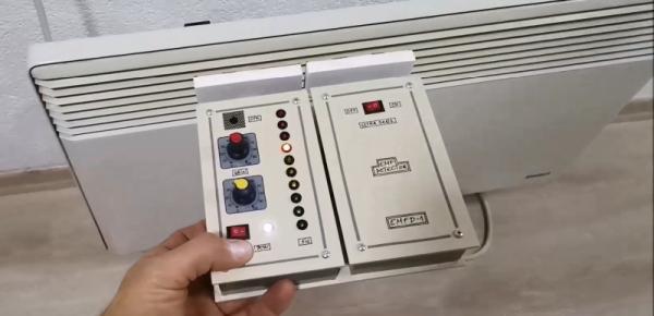
Making the whole device work reliably was an interesting exercise in electromagnetic engineering: in the first few iterations, the detector would trigger off its own LEDs and buzzer, trapping itself in a never-ending loop. [Mirko] solved this by encasing the Arduino inside a closed, grounded metal box with only the required wires sticking out. The antenna’s design was largely based on trial-and-error; the current setup with a 7 cm x 3 cm piece of aluminium sheet seemed to work well.
While this is not a calibrated professional-grade instrument, it should come in handy to find sources of interference, or even simply to locate hidden power cables. You can view this as a more advanced version of [Mirko]’s Junk Box EMF Detector; if you have a second Arduino lying around, you can use that one to generate interference instead.
Source: MEASURING ELECTROMAGNETIC FIELDS WITH JUST AN ARDUINO AND A PIECE OF WIRE
- How does the device detect electromagnetic fields?
It connects an antenna directly to the Arduino's high impedance analog input to visualize measured signals. - Why is a resistor required in the circuit?
A resistor of a few mega-Ohms to ground prevents the sensor from triggering on random noise due to high sensitivity. - Can the detector be used in noisy environments?
Yes, resistance is made adjustable with knobs and switches to handle both quiet and noisy settings. - What issue occurred during initial testing?
The detector triggered off its own LEDs and buzzer, creating a never-ending feedback loop. - How was the self-interference problem solved?
Mirko encased the Arduino inside a closed, grounded metal box with only necessary wires sticking out. - What material was used for the antenna?
The current setup uses a 7 cm x 3 cm piece of aluminium sheet. - Is this device a calibrated professional instrument?
No, it is not a calibrated professional-grade instrument but is useful for finding interference sources. - What is one practical use of this detector?
It can be used to locate hidden power cables or find sources of interference.