The following instructable describes a easy to build and inexpensive device to perform pressure measurements and demonstrate Boyle’s law, using the micro:bit in combination with the BMP280 pressure/temperature sensor.
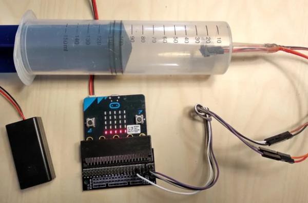
Whereas this syringe/pressure sensor combination has already been described in one of my previous instructables, the combination with the micro:bit is offering new opportunities, e.g. for class room projects.
In addition, the number of descriptions of applications in which the micro:bit is used in combination with a I2C driven sensor are rather limited so far. I hope this instructable might be a starting point for other projects.
The device allows to perform quantitative air pressure measurements, and to display the results on the micro:bit LED array or on a connected computer, for the later using the serial monitor or serial plotter functions of the Arduino IDE. In addition you have a haptic feedback, as you will push or pull the plunger of the syringe yourself, and hereby feel the required power.
By default, the display allows you to estimate the pressure by the level indicator shown on the LED matrix. The serial plotter of the Arduino IDE allows to do the same, but with much better resolution (see video). More elaborate solutions are also available, e.g. in the Processing language. You also can display the precise measured values of pressure and temperature on the LED matrix after pressing the A or B buttons respectively, but the serial monitor of the Arduino IDE is much faster, allowing to display values in near real time.
Total costs and the technical skills required to build the device are rather low, so it could be a nice classroom project under supervision of a teacher. In addition the device could be a tool for STEM projects with focus on physics or used in other projects where a force or weight shall be transformed into a digital value.
The principle was used to construct a very simple micro:bit dive-o-meter, a device to measure how deep you are diving.
Addendum 27-May-2018:
As Pimoroni has developed a MakeCode library for the BMP280 sensor, This gave me the opportunity to develop a script to be used for the device described here. The script and the corresponding HEX-file can be found in the last step of this instructable. To use it, just load the HEX file to your micro:bit. No need for special software, and you may use the online MakeCode editor for editing the script.
Step 1: Used Materials
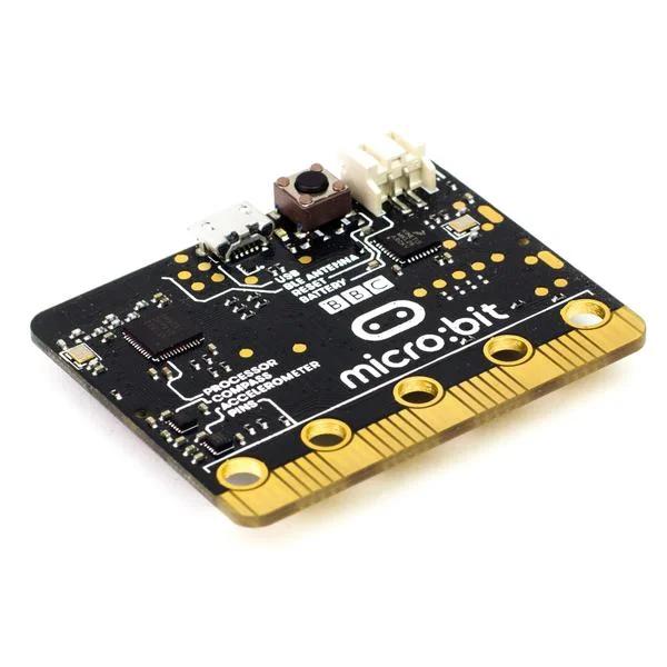
- A micro:bit, got mine from Pimoroni – 13.50 GBP
- Kitronic Edge Connector for micro:bit – via Pimoroni – 5 GBP,
Remark: Pimorini now offers a breadboard-friendly edge connector called pin:bit with pins on the I2C ports. - 2 x 2 pin header strips
- Battery or LiPo for the micro:bit (not necessary, but helpful), battery cable with switch (dito) – Pimoroni
- jumper cables for connection of sensors to Edge connector
- long (!) jumper cables for the sensor, at least as long as the syringe,, f/f or f/m
- BMP280 pressure & temperature sensor – Banggood – 5 US$ for three units
The measurement range for this sensor is between 550 and 1537 hPa. - 150 ml plastic catheter syringe with rubber gasket – Amazon or hardware and garden shops – about 2 – 3 US$
- hot glue/hot glue pistol
- soldering iron
- a computer with the Arduino IDE installed
Step 2: Assembly Instructions
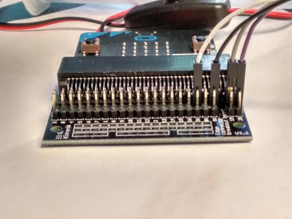
Solder headers to the BMP280 sensor breakout.
Solder the two 2 pin headers to the pin 19 and pin 20 connectors of the Edge connector (see image).
Connect the micro:bit to the Edge connector and your computer.
Prepare software and micro:bit as described in the Adafruit micro:bit instructions. Read them thoroughly.
Install the required libraries to the Arduino IDE.
Open the BMP280 script attached in a later step.
Connect the sensor to the Edge connector. GND to 0V, VCC to 3V, SCL to pin 19, SDA to pin 20.
Upload the script to the micro:bit.
Check that the sensor gives reasonable data, pressure values should be around 1020 hPa, displayed on the serial monitor. In case, check cables and connections first, then software installation, and correct.
Turn off micro:bit, remove sensor.
Run the long jumper cables through the outlet of the syringe. In case you may have to widen the opening. Be careful to omit that the cables are getting damaged.
Connect the sensor to the jumper cables. Check that connections are correct and good. Connect to the micro:bit.
Check that sensor is running correctly. Carefully pulling the cables, move the sensor to the top of the syringe.
Insert plunger and move it a bit further than the desired resting position (100 ml).
Add hot glue to the end of the syringe outlet and move the plunger back a bit. Check if the syringe is closed air tight, otherwise add more hot glue. Let cool the hot glue.
Check again that the sensor is working. If you move the plunger, the numbers in the serial monitor and the micro:bit’s display should change.
If required you may adjust the volume in the syringe by squeezing it near the gasket and moving the plunger.
Step 3: A Bit of Theory and Some Practical Measurements
With the device described here, you can demonstrate the correlation of compression and pressure in simple physics experiments. As the syringe comes with a “ml”-scale on it, even quantitative experiments are easy to perform.
The theory behind it:
According to Boyle’s law, [Volume * Pressure] is a constant value for a gas at a given temperature.
This means if you compress a given volume of gas N-fold, i.e. the final volume is 1/N fold of the original, its pressure will go up N-fold, as: P0*V0=P1*V1= const. For more details, please have a look on the Wikipedia article on gas laws. At sea level, the barometric pressure is usually in the range of 1010 hPa (hecto Pascal).
So starting at a resting points of e.g. V0=100 ml and P0=1000 hPa, a compression of the air to about 66 ml (i.e. V1 = 2/3 * V0) will result in a pressure of about 1500 hPa (P1= 3/2 of P0). Pulling the plunger to 125 ml (5/4 fold volume) results in a pressure of about 800 hPa (4/5 pressure). The measurements are astonishingly precise for such a simple device.
The device allows you to have a direct haptic impression how much force is required to compress or expand the relatively small amount of air in the syringe.
But we also can perform some calculations and check them experimentally. Assume we compress the air to 1500 hPa, at a basal barometric pressure of 1000 hPa. So the pressure difference is 500 hPa, or 50,000 Pa. For my syringe, the diameter (d) of the piston is about 4 cm or 0.04 meter.
Now you can calculate the force required to hold the piston in that position. Given P = F/A (Pressure is Force divided by Area), or transformed F = P*A. The SI unit for force is “Newton” N, for length “Meter” m, and 1 Pa is 1N per square meter. For a round piston, the area can be calculated using A = ((d/2)^2)*pi , which gives 0.00125 square meters for my syringe. So
50,000 Pa * 0.00125 m^2 = 63 N.
On Earth, 1 N correlates to a weight of 100 gr, so 63 N are equal to holding a weight of 6.3 kg.
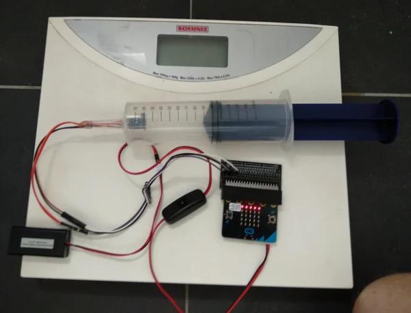
This can be checked easily using a scale. Push the syringe with the plunger onto the scale, until a pressure of about 1500 hPa is reached, then read the scale. Or push until the scale shows about 6-7 kg, then press the “A” button and read the value displayed on the micro:bit’s LED matrix. As it turned out, the estimation based on the above calculations were not bad. A pressure slightly above 1500 hPa correlated to a displayed “weight” of about 7 kg on a body scale (see images). You also could turn this concept around and use the device to build a simple digital scale based on pressure measurements.
Please be aware that the upper limit for the sensor is about 1540 hPa, so any pressure above this can not be measured and may damage the sensor.
Beside educational purposes, one may also use the system for some real world applications, as it does allow to quantitatively measure forces that are trying to move the plunger one way or the other. So you could measure a weight placed on the plunger or an impact force hitting on the plunger. Or build a switch that activates a light or buzzer or plays a sound after a certain threshold value was reached. Or you could build a musical instrument that changes the frequency depending on the strength of force applied to the plunger. Or use it as a game controller.
Use your imagination and play!
Step 4: The MicroPython Script
Attached you find my BMP280 script for the micro:bit. It is a derivate of a BMP/BME280 script I found somewhere the Banggood website, combined with Adafruit’s Microbit library. The first allows you to use the Banggood sensor, the second simplifies handling of the 5×5 LED display. My thanks go to the developers of both.
By default, the script displays the results of pressure measurements in 5 steps on the micro:bit’s 5×5 LED display, allowing to see changes with little delay. The precise values can be displayed in parallel on the Arduino IDE serial monitor, or a more detailed graph can be displayed the seral plotter of the Arduino IDE.
If you press the A button, the measured pressure values are displayed on the micro:bit’s 5×5 LED array. If you press the B button, the temperature values are displayed. While this allows to read the precise data, is slows down the measurement cycles significantly.
I am sure that there are much more elegant ways to program the tasks and improve the script. Any help is welcome.
#include xxx
#include Adafruit_Microbit_Matrix microbit;
#define BME280_ADDRESS 0x76
unsigned long int hum_raw,temp_raw,pres_raw;
signed long int t_fine;
uint16_t dig_T1;
 int16_t dig_T2;
 int16_t dig_T3;
uint16_t dig_P1;
 int16_t dig_P2;
 int16_t dig_P3;
 int16_t dig_P4;
 int16_t dig_P5;
 int16_t dig_P6;
 int16_t dig_P7;
 int16_t dig_P8;
 int16_t dig_P9;
 int8_t  dig_H1;
 int16_t dig_H2;
 int8_t  dig_H3;
 int16_t dig_H4;
 int16_t dig_H5;
 int8_t  dig_H6;
// containers for measured values
 int value0;
 int value1;
 int value2;
 int value3;
 int value4;
//--------------------------------------------------------------------------------------------------------------------
void setup()
{
    uint8_t osrs_t = 1;             //Temperature oversampling x 1
    uint8_t osrs_p = 1;             //Pressure oversampling x 1
    uint8_t osrs_h = 1;             //Humidity oversampling x 1
    uint8_t mode = 3;               //Normal mode
    uint8_t t_sb = 5;               //Tstandby 1000ms
    uint8_t filter = 0;             //Filter off
    uint8_t spi3w_en = 0;           //3-wire SPI Disable
    uint8_t ctrl_meas_reg = (osrs_t << 5) | (osrs_p << 2) | mode;
    uint8_t config_reg    = (t_sb << 5) | (filter << 2) | spi3w_en;
    uint8_t ctrl_hum_reg  = osrs_h;
    pinMode(PIN_BUTTON_A, INPUT);
    pinMode(PIN_BUTTON_B, INPUT);
    Serial.begin(9600);
 //   Serial.println("Temperature [deg C]");
 //   Serial.print("\t");
    Serial.print("Pressure [hPa] ");   // header

    Wire.begin();
    writeReg(0xF2,ctrl_hum_reg);
    writeReg(0xF4,ctrl_meas_reg);
    writeReg(0xF5,config_reg);
    readTrim();                    //
    microbit.begin();
//    microbit.print("x");
    delay (1000);
}
//---------------------------------------------------------------------------------------------------------
void loop()
{
    double temp_act = 0.0, press_act = 0.0,hum_act=0.0;
    signed long int temp_cal;
    unsigned long int press_cal,hum_cal;
    int N;

    // set threshold values for LED matrix display, in hPa
    double max_0 = 1100;
    double max_1 = 1230;
    double max_2 = 1360;
    double max_3 = 1490;

    readData();
    temp_cal = calibration_T(temp_raw);
    press_cal = calibration_P(pres_raw);
    hum_cal = calibration_H(hum_raw);
    temp_act = (double)temp_cal / 100.0;
    press_act = (double)press_cal / 100.0;
    hum_act = (double)hum_cal / 1024.0;
    microbit.clear(); //reset LED matrix

/*
    Serial.print ("PRESS : ");
    Serial.println(press_act);
    Serial.print(" hPa  ");   Serial.print("TEMP : ");
    Serial.print("\t");
    Serial.println(temp_act);
*/

   if (! digitalRead(PIN_BUTTON_B)) {
//  displaying values in numbers delays measuring circles
    microbit.print("T: ");
    microbit.print(temp_act,1);
    microbit.print(" 'C");
//  Serial.println("");
   }else if (! digitalRead(PIN_BUTTON_A)) {
    microbit.print("P: ");
    microbit.print(press_act,0);
    microbit.print(" hPa");
  }else{
 // displaying pressure values as pixels or lines in a certain level
// 5 steps: <1100 hPa, 1101 - 1230 pPa, 1231 - 1360 hPa, 1361 - 1490 hPa, >1490 hPa
// thresholds defined by the max_n values
    if (press_act > max_3){
      (N=0);                            // upper row
    } else if (press_act > max_2){
      (N=1);
    } else if (press_act > max_1){
      (N=2);
    } else if (press_act > max_0){
      (N=3);
    } else {
      (N=4);                          // base row
    }
//    Serial.println(N);   // for development purposes
//    microbit.print(N);

//    as Line
//    microbit.drawLine(N,0,0,4, LED_ON);
// shift values to next line
   value4 = value3;
   value3 = value2;
   value2 = value1;
   value1 = value0;
   value0 = N;
// draw image, column by column
   microbit.drawPixel(0,value0, LED_ON); // as Pixel: column, row. 0,0 left upper corner
   microbit.drawPixel(1,value1, LED_ON);
   microbit.drawPixel(2,value2, LED_ON);
   microbit.drawPixel(3,value3, LED_ON);
   microbit.drawPixel(4,value4, LED_ON);
  }

//  send data to serial monitor and serial plotter
//  Serial.println(press_act);    // send value(s) to serial port for numeric display, optional
</p><p>    Serial.print(press_act); // send value to serial port for plotter
// draw indicator lines and fix displayed range
    Serial.print("\t"); Serial.print(600);
    Serial.print("\t"); Serial.print(1100),
    Serial.print("\t"); Serial.println(1600);

   delay(200);      // Measure three times a second
}
//----------------------------------------------------------------------------------------------------------------------------------------------
//  the following is required for the bmp/bme280 sensor, keep as it is
void readTrim()
{
    uint8_t data[32],i=0;                      // Fix 2014/04/06
    Wire.beginTransmission(BME280_ADDRESS);
    Wire.write(0x88);
    Wire.endTransmission();
    Wire.requestFrom(BME280_ADDRESS,24);       // Fix 2014/04/06
    while(Wire.available()){
        data[i] = Wire.read();
        i++;
    }
    Wire.beginTransmission(BME280_ADDRESS);    // Add 2014/04/06
    Wire.write(0xA1);                          // Add 2014/04/06
    Wire.endTransmission();                    // Add 2014/04/06
    Wire.requestFrom(BME280_ADDRESS,1);        // Add 2014/04/06
    data[i] = Wire.read();                     // Add 2014/04/06
    i++;                                       // Add 2014/04/06
    Wire.beginTransmission(BME280_ADDRESS);
    Wire.write(0xE1);
    Wire.endTransmission();
    Wire.requestFrom(BME280_ADDRESS,7);        // Fix 2014/04/06
    while(Wire.available()){
        data[i] = Wire.read();
        i++;
    }
    dig_T1 = (data[1] << 8) | data[0];
    dig_P1 = (data[7] << 8) | data[6];
    dig_P2 = (data[9] << 8) | data[8];
    dig_P3 = (data[11]<< 8) | data[10];
    dig_P4 = (data[13]<< 8) | data[12];
    dig_P5 = (data[15]<< 8) | data[14];
    dig_P6 = (data[17]<< 8) | data[16];
    dig_P7 = (data[19]<< 8) | data[18];
    dig_T2 = (data[3] << 8) | data[2];
    dig_T3 = (data[5] << 8) | data[4];
    dig_P8 = (data[21]<< 8) | data[20];
    dig_P9 = (data[23]<< 8) | data[22];
    dig_H1 = data[24];
    dig_H2 = (data[26]<< 8) | data[25];
    dig_H3 = data[27];
    dig_H4 = (data[28]<< 4) | (0x0F & data[29]);
    dig_H5 = (data[30] << 4) | ((data[29] >> 4) & 0x0F); // Fix 2014/04/06
    dig_H6 = data[31];                                   // Fix 2014/04/06
}
void writeReg(uint8_t reg_address, uint8_t data)
{
    Wire.beginTransmission(BME280_ADDRESS);
    Wire.write(reg_address);
    Wire.write(data);
    Wire.endTransmission();
}</p><p>void readData()
{
    int i = 0;
    uint32_t data[8];
    Wire.beginTransmission(BME280_ADDRESS);
    Wire.write(0xF7);
    Wire.endTransmission();
    Wire.requestFrom(BME280_ADDRESS,8);
    while(Wire.available()){
        data[i] = Wire.read();
        i++;
    }
    pres_raw = (data[0] << 12) | (data[1] << 4) | (data[2] >> 4);
    temp_raw = (data[3] << 12) | (data[4] << 4) | (data[5] >> 4);
    hum_raw  = (data[6] << 8) | data[7];
}</p><p>signed long int calibration_T(signed long int adc_T)
{
    signed long int var1, var2, T;
    var1 = ((((adc_T >> 3) - ((signed long int)dig_T1<<1))) * ((signed long int)dig_T2)) >> 11;
    var2 = (((((adc_T >> 4) - ((signed long int)dig_T1)) * ((adc_T>>4) - ((signed long int)dig_T1))) >> 12) * ((signed long int)dig_T3)) >> 14;
    t_fine = var1 + var2;
    T = (t_fine * 5 + 128) >> 8;
    return T;
}
unsigned long int calibration_P(signed long int adc_P)
{
    signed long int var1, var2;
    unsigned long int P;
    var1 = (((signed long int)t_fine)>>1) - (signed long int)64000;
    var2 = (((var1>>2) * (var1>>2)) >> 11) * ((signed long int)dig_P6);
    var2 = var2 + ((var1*((signed long int)dig_P5))<<1);
    var2 = (var2>>2)+(((signed long int)dig_P4)<<16);
    var1 = (((dig_P3 * (((var1>>2)*(var1>>2)) >> 13)) >>3) + ((((signed long int)dig_P2) * var1)>>1))>>18;
    var1 = ((((32768+var1))*((signed long int)dig_P1))>>15);
    if (var1 == 0)
    {
        return 0;
    }
    P = (((unsigned long int)(((signed long int)1048576)-adc_P)-(var2>>12)))*3125;
    if(P<0x80000000)
    {
       P = (P << 1) / ((unsigned long int) var1);
    }
    else
    {
        P = (P / (unsigned long int)var1) * 2;
    }
    var1 = (((signed long int)dig_P9) * ((signed long int)(((P>>3) * (P>>3))>>13)))>>12;
    var2 = (((signed long int)(P>>2)) * ((signed long int)dig_P8))>>13;
    P = (unsigned long int)((signed long int)P + ((var1 + var2 + dig_P7) >> 4));
    return P;
}
unsigned long int calibration_H(signed long int adc_H)
{
    signed long int v_x1;
    v_x1 = (t_fine - ((signed long int)76800));
    v_x1 = (((((adc_H << 14) -(((signed long int)dig_H4) << 20) - (((signed long int)dig_H5) * v_x1)) +
              ((signed long int)16384)) >> 15) * (((((((v_x1 * ((signed long int)dig_H6)) >> 10) *
              (((v_x1 * ((signed long int)dig_H3)) >> 11) + ((signed long int) 32768))) >> 10) + (( signed long int)2097152)) *
              ((signed long int) dig_H2) + 8192) >> 14));
   v_x1 = (v_x1 - (((((v_x1 >> 15) * (v_x1 >> 15)) >> 7) * ((signed long int)dig_H1)) >> 4));
   v_x1 = (v_x1 < 0 ? 0 : v_x1);
   v_x1 = (v_x1 > 419430400 ? 419430400 : v_x1);
   return (unsigned long int)(v_x1 >> 12);
}
Step 5: MakeCode/JavaScript Scripts
Pimoroni has recently released the enviro:bit, that comes with a BMP280 pressure sensor, a light/color sensor and a MEMS microphone. They also offer a MicroPython and a MakeCode/JavaScript library.
I used the later to write a MakeCode script for the pressure sensor. The corresponding hex file can be copied directly to your micro:bit. The code is displayed below and may be modified using the online MakeCode editor.
It is a variation of the script for the micro:bit dive-o-meter. By default it displays the pressure difference as a bar graph. Pressing button A sets the reference pressure, pressing button B displays the difference between the actual and the reference pressure in hPa.
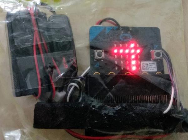
In addition to the basic barcode version you also find a “X”, crosshair version and a “L” version, intended to make reading easier.
let Column = 0
let remain = 0
let Row = 0
let Meter = 0
let Delta = 0
let Ref = 0
let Is = 0
Is = 1012
basic.showLeds(`
    # # # # #
    # . . . #
    # . # . #
    # . . . #
    # # # # #
    `)
Ref = 1180
basic.clearScreen()
basic.forever(() => {
    basic.clearScreen()
    if (input.buttonIsPressed(Button.A)) {
        Ref = envirobit.getPressure()
        basic.showLeds(`
            # . # . #
            . # . # .
            # # # # #
            . # . # .
            # . # . #
            `)
        basic.pause(1000)
    } else if (input.buttonIsPressed(Button.B)) {
        basic.showString("" + Delta + " hPa")
        basic.pause(200)
        basic.clearScreen()
    } else {
        Is = envirobit.getPressure()
        Delta = Is - Ref
        Meter = Math.abs(Delta)
        if (Meter >= 400) {
            Row = 4
        } else if (Meter >= 300) {
            Row = 3
        } else if (Meter >= 200) {
            Row = 2
        } else if (Meter >= 100) {
            Row = 1
        } else {
            Row = 0
        }
        remain = Meter - Row * 100
        if (remain >= 80) {
            Column = 4
        } else if (remain >= 60) {
            Column = 3
        } else if (remain >= 40) {
            Column = 2
        } else if (remain >= 20) {
            Column = 1
        } else {
            Column = 0
        }
        for (let ColA = 0; ColA <= Column; ColA++) {
            led.plot(ColA, Row)
        }
        basic.pause(500)
    }
})