Summary of how to measure home ac current 110v / 200v with arduino
This tutorial explains using an ACS712 hall-effect sensor with an Arduino to measure AC mains current by sampling to find positive and negative peaks, computing peak-to-peak voltage, converting to RMS volts for a sine wave, and applying the ACS712 scale factor to get Amps RMS. It includes sourcing, safety notes, sampling guidance, Arduino code (getVPP function samples for 1 second), and the conversion steps.
Parts used in the ACS712 AC Measurement Tutorial:
- ACS712 current sensor module (various current ratings)
- Arduino (any with analog input A0)
- Connecting wires
- Load to measure (AC mains load)
- USB cable or power supply for Arduino
- Serial monitor (software on connected PC)
The cool thing about an ACS712 is that current is measured is measured in two directions. What this means is that if we sample fast enough and long enough, we sure to find the peak in one direction and the peak in another direction.
With both peaks known, it is a matter of knowing the shape of the waveform to calculate the current. In the case of line or mains power, we know that waveform to be a SINE wave. Knowing that allows us to apply a basic electronic formula to yield a decent result.

This tutorial will show you how this is done.
Getting an ACS712
They are readily available at any of the following vendors:
Amazon
Discussion of the Basic Methology Applied
Finding the RMS Value
In most cases, an expression of AC current will be in a value known as RMS. In order to use the ACS712 current sensor to measure AC current, it is important to understand how to calculate an RMS current value from the device readings.
The formula that is applied here is very basic and is right out of any basic electricity or electronics manual.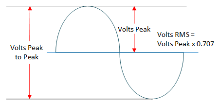
With an ACS712, current measurements are reported with a voltage output. In this tutorial, we will calculate the RMS volts and apply the ACS712 scale factor.
Conversion for a sine wave with a zero volt offset (like your mains or line power) is performed as follows…
1) Find the peak to peak voltage ( Volts Peak to Peak )
2) Divide the peak to peak voltage by two to get peak voltage (Volts Peak)
3) Multiply the peak voltage by 0.707 to yield rms volts (Volts RMS)
Having Calculated RMS voltage, is simply a matter of multiplying by the scale factor of the particular ACS712 to yield the RMS value of the current being measured.
Arduino Sampling for the Peaks
The values out of the ACS712 are constantly changing when measuring AC Current. In order ensure that you have come very close to finding the peaks, you need to sample fast enough and long enough. Because mains or line power is at a frequency of 50 to 60 hz, the Arduino will be fast enough provided it takes consecutive samples with little or no interruption.
In this tutorial, there is a function dedicated to doing just that.
Arduino ACS712 Current Measurement Tutorial
NOTE: This works for lower voltage measurements and perhaps experimentally at a higher line voltage. This should not be used in a permanent line voltage application.
Arduino ACS712 AC Measurement Tutorial Setup
Fundamental to performing this tutorial safely is knowing what the current rating of your ACS712 and the amount of current that your load requires.
Connect the components as shown below: 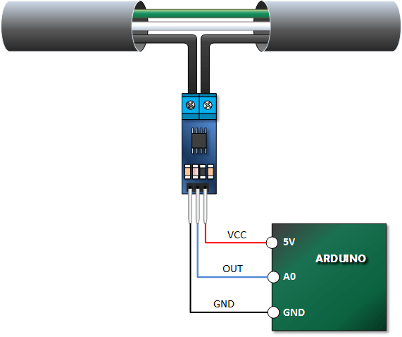
The ACS712 Arduino AC Current Tutorial Sketch
Copy, Paste and Upload the code below. Also take a look at how I make a call to the ‘getVPP‘ function from the main loop. In that function, I take interupted AC samples for one second while recording the maximum and minimum values. From this I will calculate the peak to peak voltage measured. I’ve found this to be extremely effective for line power frequencies.
Mind you, my power is pretty clean. If you’ve got a lot of spikes, getting a meaningful measurement could be tough.
/*
Measuring AC Current Using ACS712
*/
const int sensorIn = A0;
int mVperAmp = 185; // use 100 for 20A Module and 66 for 30A Module


double Voltage = 0;
double VRMS = 0;
double AmpsRMS = 0;


void setup(){
 Serial.begin(9600);
}

void loop(){


 Voltage = getVPP();
 VRMS = (Voltage/2.0) *0.707;
 AmpsRMS = (VRMS * 1000)/mVperAmp;
 Serial.print(AmpsRMS);
 Serial.println(" Amps RMS");

}

float getVPP()
{
  float result;

  int readValue;             //value read from the sensor
  int maxValue = 0;          // store max value here
  int minValue = 1024;          // store min value here

   uint32_t start_time = millis();
   while((millis()-start_time) < 1000) //sample for 1 Sec
   {
       readValue = analogRead(sensorIn);
       // see if you have a new maxValue
       if (readValue > maxValue)
       {
           /*record the maximum sensor value*/
           maxValue = readValue;
       }
       if (readValue < minValue)
       {
           /*record the maximum sensor value*/
           minValue = readValue;
       }
   }

   // Subtract min from max
   result = ((maxValue - minValue) * 5.0)/1024.0;

   return result;
 }
- How does the ACS712 measure AC current in two directions?
The ACS712 outputs a voltage proportional to current in both polarities, allowing detection of peaks in each direction when sampled fast enough. - How do you calculate RMS current from ACS712 readings?
Find peak-to-peak voltage, divide by two to get peak voltage, multiply by 0.707 for RMS volts, then multiply by the ACS712 scale factor to get Amps RMS. - How long should the Arduino sample to find peaks for mains power?
The tutorial samples continuously for one second to reliably capture peaks at 50–60 Hz mains frequency. - Can the provided Arduino code measure mains AC current?
Yes; the sketch samples A0 for one second using getVPP, computes VRMS and AmpsRMS, and prints Amps RMS to the serial monitor. - What ACS712 scale factors are used in the code?
The code uses mVperAmp = 185 by default and notes 100 for the 20A module and 66 for the 30A module. - Does the tutorial address measurement accuracy with noisy waveforms?
Yes; it notes that measurements are effective for clean mains and that spikes or noise can make meaningful measurement difficult. - Can this method be used for permanent line voltage installations?
No; the tutorial warns against using this in permanent line voltage applications and suggests experimental or lower voltage use.