ESP-01 ESP8266 is a popular and widely used module because of its low-cost, reliability and easily availability in the market. It can be used as a stand-alone device or connected with a microcontroller. The ESP-01 is the smallest ESP8266 module and it has limited I/Os. It has totally 8 pins, four of them are needed for module operation (VCC, GND, RST and CH_PD), and remaining four pins (GPIO0, GPIO2, TX and RX) can be used as programmable GPIOs pins but even they have pre-assigned functions as follows:
- The GPIO0 and GPIO2 check & determine which mode that the ESP8266 needs to enter when ESP8266-01 booting up. During the normal operating mode, the GPIO0 and GPIO2 will be high, and grounding GPIO0 sets the chip to programming mode.
- The TX/RX pins are used to program the module and for Serial I/O, commonly used for debugging.
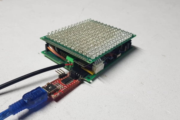
I have referenced many articles on how to use these 4 pins on ESP-01 and realize that we can do a lot of things with only those 4 pins. Today, I’m willing to share how ESP-01 can be used as a stand-alone device to control a led matrix 13×15 and even at the same time it can get and show time information, weather information on this led matrix via WIFI.
Let’s getting started.
RGB LED CUBE 4x4x4 with ESP-01S ESP8266 (Update on June 16, 2020).
Step 1: THINGS WE NEED
ELECTRONIC COMPONENTS:
- 200PCS X LED 3MM, BLUE COLOR IN MY CASE.
- 02PCS X DOUBLE SIDE DIY PROTOBOARD CIRCUIT 7X9CM.
- 01PCS X ESP-01 ESP8266.
- 01PCS X AMS1117 3.3V POWER SUPPLY MODULE.
- 02PCS X SHIFT REGISTER 74HC595.
- 02PCS X POWER LOGIC 8-BIT SHIFT REGISTER TPIC6B595N.
- 16PCS X TRANSISTOR A1013.
- 16PCS X R100.
- 20PCS X R1K.
- 04PCS X CAPACITOR 1UF.
- 02PCS X FEMALE 40PIN 2.54MM HEADER.
- 02PCS X MALE 40PIN 2.54MM HEADER.
- 01PCS X PUSH BUTTON.
- 01PCS X SLIDE SWITCH.
- 01PCS X 2PIN 5.08MM PITCH SCREW TERMINAL BLOCK.
- 01METER X 8P RAINBOW RIBBON CABLE.
PROGRAMMING TOOL FOR ESP-01 ESP8266:
- 01PCS X FTDI FT232RL USB TO TTL SERIAL ADAPTER.
- 01PCS X USB CABLE MINI TYPE B TO TYPE A.
You can download the schematic in high resolution HERE, it includes:
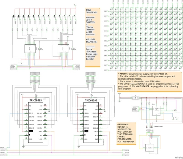
1. LED MATRIX MODULE:
It includes 195 LEDs arranged in 13 ROWS and 15 COLUMNS. The reason is that my PROTOBOARD CIRCUIT 7X9CM can only fit this size even though my control board below can control led matrix module upto size 16×16.
2. CONTROL MODULE:
- ROW SCANNING (TO LED ANODES): including 2pcs x 74HC595 + 13pcs x Transitor A1013. Outputs from PNP transistors A1013 are connected to 13 LED ROWS (ANODES), so the row needs to be HIGH for an individual LED to turn on. The PNP transistors A1013 can carry maximum collector current about 1A. If the row and column are either HIGH or LOW, no voltage flows through the LED and it doesn’t turn on.
- COLUMN SCANNING (TO LED CATHODES): including 2pcs x TPIC6B595N Power Logic 8-Bit Shift Register. Outputs from TPIC6B595N are connected to 15 LED COLUMNS (CATHODES) through current limiting resistors R100, so a column needs to be LOW for any of the LEDs in that column to turn on. High power shift register TPIC6B595N is high power drains, able to sink 150mA per pin and it cannot source current so they should be connected to LED cathodes.
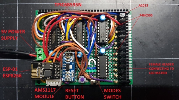
- ESP-01 ESP8266 including modes slide switch, reset button, programming header and AMS1117 power module for converting from 5V to 3.3V.
The schematic below is shown how the ESP-01 can boot up in program mode and normal operation mode:
- The button – S1 – is used to reset ESP-01.
- The slide switch – S2 – allows switching between program and normal operation modes.
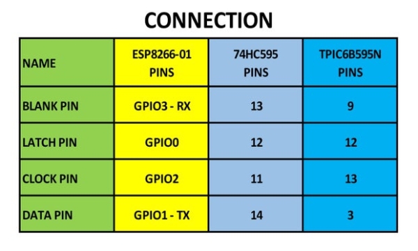
- In normal operation mode, ESP-01 control 13xrows and 15xcolumns of led matrix by 4 GPIO pins as follows:
– BLANK PIN connecting to GPIO3 – RX
– LATCH PIN connecting to GPIO0
– CLOCK PIN connecting to GPIO2
– DATA PIN connecting to GPIO1 – TX
NOTES:
- AMS1117 power module is used for supplying 3.3V to ESP-01.
- All pull-up resistors are 10Kohm.
- The 6 PIN FEMALE PROGRAMMING HEADER was soldered on control board. We can easily plug FTDI programmer into this header and switch S2 to GND position for uploading our program from Arduino IDE.
Step 3: SOLDERING
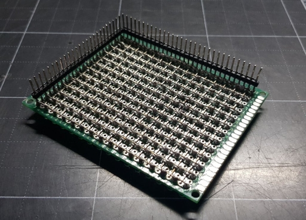
1. LED MATRIX MODULE:
You can check at my previous instructable to know how to solder the matrix 13×15: https://www.instructables.com/id/LED-MATRIX-SHIELD…
- TOP VIEW
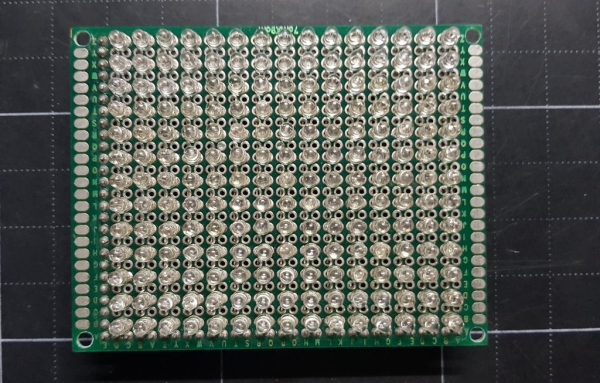
- BOTTOM VIEW:
Take note that male headers for rows and columns of led module are soldered at bottom, it will be connected to control board.
2. CONTROL MODULE:
Soldering the control module following the schematic on previous step. You have to solder very carefully, it takes your time and your effort….
- TOP VIEW
Step 4: PROGRAMMING
In my program, ESP-01 ESP8266 is used as a stand-alone device. It gets and shows time information, weather information on led matrix 13×15 from NTP server and openweathermap. The project code is available at my GitHub.
CONNECTION
The ESP-01 ESP8266, 74HC595 & TPIC6B595N are connected together as follows:
LIBRARIES
// ESP-01 ESP8266 WiFi Main Library
#include <ESP8266WiFi.h>

// Libraries for Internet NTP Time
#include <NTPClient.h>
#include <WiFiUdp.h>
#include <time.h>

// Libraries for Internet Weather
#include <ESP8266HTTPClient.h>
#include <ArduinoJson.h>
LED MATRIX CONTROL
For row scanning (anodes), because my led matrix module has 13 rows, so we need to shift out 2 bytes to 2x74HC595 with order from 0 ~ 12, as anode array below.
byte anode[16][2]={
{B11111111, B11111110}, {B11111111, B11111101}, {B11111111, B11111011}, {B11111111, B11110111},
{B11111111, B11101111}, {B11111111, B11011111}, {B11111111, B10111111}, {B11111111, B01111111},
{B01111110, B11111111}, {B11111101, B11111111}, {B11111011, B11111111}, {B11110111, B11111111},
{B11101111, B11111111}, {B11011111, B11111111}, {B10111111, B11111111}, {B01111111, B11111111}
};
For example, if we want set row_0 to “ON“, we will write to 2 x 74HC595 shift register the value: {B11111111, B11111110} with anode low byte B11111110 and anode high byte B11111111.
I also applied the B.A.M method in this program so I can easily adjust the brightness of led matrix.
void ICACHE_RAM_ATTR timer1_ISR(void)
{
  digitalWrite(BLANK_Pin, HIGH);

  if(BAM_Counter==8)    // Bit weight 2^0 of BAM_Bit, lasting time = 8 ticks x interrupt interval time
  BAM_Bit++;
  else
  if(BAM_Counter==24)   // Bit weight 2^1 of BAM_Bit, lasting time = 24 ticks x interrupt interval time
  BAM_Bit++;
  else
  if(BAM_Counter==56)   // Bit weight 2^3 of BAM_Bit, lasting time = 56 ticks x interrupt interval time
  BAM_Bit++;
  BAM_Counter++;
  switch (BAM_Bit)
    {
    case 0:
        DIY_SPI(matrixBuffer[0][level + 0]);
        DIY_SPI(matrixBuffer[0][level + 1]);
      break;
    case 1:
        DIY_SPI(matrixBuffer[1][level + 0]);
        DIY_SPI(matrixBuffer[1][level + 1]);
      break;
    case 2:
        DIY_SPI(matrixBuffer[2][level + 0]);
        DIY_SPI(matrixBuffer[2][level + 1]);
      break;
    case 3:
        DIY_SPI(matrixBuffer[3][level + 0]);
        DIY_SPI(matrixBuffer[3][level + 1]);

    if(BAM_Counter==120)    //Bit weight 2^3 of BAM_Bit, lasting time = 120 ticks x interrupt interval time
    {
    BAM_Counter=0;
    BAM_Bit=0;
    }
    break;
  }
  // Row scanning low byte and high byte
  DIY_SPI(anode[row][0]);
  DIY_SPI(anode[row][1]);

  digitalWrite(LATCH_Pin, HIGH);
  //delayMicroseconds(2);
  digitalWrite(LATCH_Pin, LOW);
  //delayMicroseconds(2);
  digitalWrite(BLANK_Pin, LOW);

  row++;
  level = row * 2;
  if (row == 13) row=0;
  if (level == 26) level=0;

  pinMode(BLANK_Pin, OUTPUT);
  timer1_write(500);
}
I referenced to original shiftOut() function in file “core_esp8266_wiring_shift.cpp” to create for my own SPI function. You can search this file on your computer or check at this LINK.
void __attribute__((optimize("O0"))) DIY_SPI(uint8_t DATA)
{
    uint8_t i;
    uint8_t val;
    for (i = 0; i<8; i++)
    {
      digitalWrite(DATA_Pin, !!(DATA & (1 << (7 - i))));
      digitalWrite(CLOCK_Pin,HIGH);
      digitalWrite(CLOCK_Pin,LOW);
    }
}
TIME INFORMATION
The led matrix displays time from NTP Time server by scrolling the messages, with with the following information:
- Year, month, day.
- Day of week.
- Hour, minute, second.
WEATHER INFORMATION
The led matrix displays weather information with selected location from openweathermap by scrolling the messages:
- Temperature in ˚C.
- Humidity in %.
- Pressure in hPa.
- Wind speed in m/s.
- Wind degree in ˚deg.
UPLOADING PROGRAM
Uploading the program by FTDI module and take notes:
- In my program, you can see that GPIO0 of ESP-01 connect to LATCH PIN of 74HC595 & TPIC6B595N for latch function and it is set HIGH and LOW (GND) during this process. As far as my reference, there is no information about how long an interval we should set GPIO0 between the HIGH and LOW level to put ESP-01 into programming mode, but with my hardware and program code it works perfectly without any errors or interruptions. When I want to upload the program, I just simply switch “modes slide switch” to GND position (GPIO0 pull down to GND) and ensure the external power is supplied to ESP-01.
- After uploading, switching slide switch to NORMAL operation and push RESET button.
Source: MAXIMIZE THE CAPABILITIES OF ESP-01 ESP8266