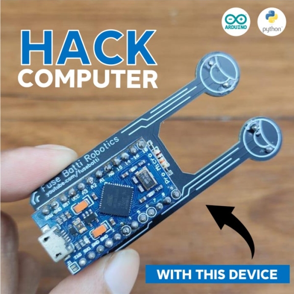
Have you ever wondered why smartphones are called smart-phones? Because they are smart, right? They do some works automatically, smartly. That’s the short answer. I was thinking something, even if computers are a lot more powerful than phones, why aren’t they smart! For instance, mobile phones have automatic brightness control system, which is handy and I use it always. But for some unknown reasons, computers don’t have automatic brightness control system. In order to change brightness, every time I have to press some buttons (function keys). And in some computers, some key combination does the work (usually fn+function-key). I find that pretty annoying. So I designed a simple device that can be connected on any pc and the pc’s brightness will be automatically controlled, just like our phones. Let’s see how I made my PC smart.
Step 1: Parts
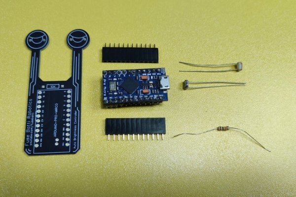
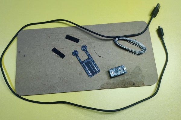
Electronics –
- Arduino (I used Pro Micro) -1x
- LDR – 2x
- 10kr – 1x
- Brightness Controller PCB [link] – 1x
- Female headers
Others –
- USB cable (compatible with Arduino board)
- Soldering tools
- And some cutting tools
That’s it.
Step 2: Principle – How Does It Work?
It’s always good to discuss about what we are making before jumping. A little theory is good enough to jump start.
I needed some kind of sensor to detect light intensity. LDR or light dependent resistor is best suited for that. LDR will face the person (just like phones sensor face front/person) and get light intensity data. The data will be read by Arduino. That’s analog data ranging from 0 to 1024.
If we map the values (0 – 1024) we can control brightness. I tried using Arduino ‘keyboard’ library to press function buttons using Arduino. That doesn’t work and it also freezes hardware keyboard (as the pc knows keyboard is already working).
So I am sending the sensor data to a python program that runs on the PC. And python does the rest, I mean controlling brightness.
Now, let’s start making.
Step 3: Making and Testing Circuit/concept
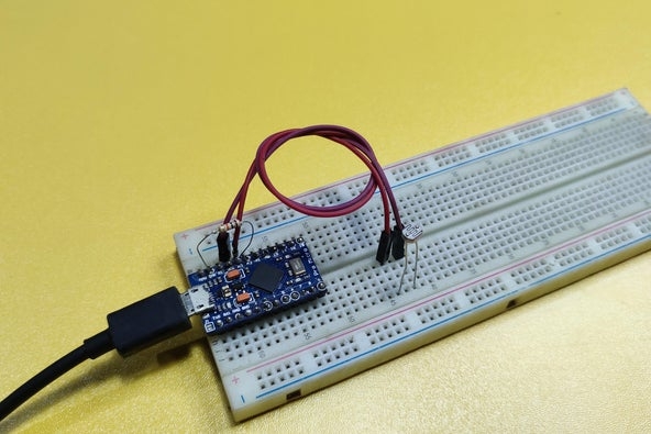
To prove my concept I first made the circuit in bread board. And wrote a simple program to output the sensor data (light intensity data) over serial monitor of Arduino.
Here’s the program that I wrote (download from github)-
// define sensor pin
int sensor_pin = A3;

void setup() {
  // set things here
  Serial.begin(9600);  // init serial communication at 9600 bps
}

void loop() {
  // mainloop
  int sensorValue = analogRead(sensor_pin); // read the input on analog pin A3:
  Serial.println(sensorValue);              // send data over serial

  delay(200);                               // a little delay to make things work better
}
And I got some output data over serial. The data ranged from 0 to 1024 (in theory). But in practical, no LDR is perfect (not even on same batch). So I got data from 0 to 950 or something. Still that works. Doesn’t matter that much in my application.
So it was a successful test and now I can proceed to next.
Step 4: Design and Make PCB
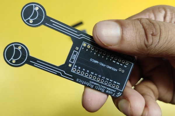
I used the same circuit on easyEDA and designed a PCB (Printed Circuit Board). You can see that I used two sensors, actually that’s just for design purpose. With two LDR it kind of looks like a snail. LDR_L is the LDR that is not being used.
Then I fabricated the PCB from PCBWay.com. PCBWay is one of the best and my favorite PCB manufacturer. With just 5$ I can get 10 PCB’s! Anyway, I used their quick order page followed by quick order pcb section, uploaded my PCB and chose color. That’s it! I think quick-order section is a blessing for all of us who don’t know much, and just want to get it done. Get the PCB from here.
I used just black earlier, it was so shiny I tried matte black this time. After waiting for around 3-4 days, I got the beautiful PCB’s. The quality is as always amazing. The pads, solder mask, silkscreen is just as perfect as they could be. I think I fell in love with matte black.
Step 5: Solder PCB and Complete Hardware
Now it’s time to solder thing in place. It’s simple as not much components are there. Soldered everything and made sure I did not inhale the smoke of soldering iron.
I used female headers as I am a plug and play guy. You can just solder the Arduino board itself on the board.
Caution: DO NOT INHALE SOLDERING IRON SMOKE! IT MAY CAUSE CANCER!
Step 6: Program the Board (Arduino Code)
Now it’s time to upload the program of Arduino. Arduino uses Serial communication to send data to PC.
First of all I defined the sensor pin, the pin of Arduino where the sensor inputs data.
// define sensor pin
int sensor_pin = A3;<br>
In setup function I started serial communication with a buad rate of 9600. Setup function runs only once every time we power the Arduino board.
void setup() {
  // set things here
  Serial.begin(9600);  // init serial communication at 9600 bps
}<br>
Then in mainloop it gets data and sends over serial. A little delay of 200ms is kept to make it work smoothly.
void loop() {
  // mainloop
  int sensorValue = analogRead(sensor_pin); // read the input on analog pin A3:
  Serial.println(sensorValue);              // send data over serial

  delay(200);                               // a little delay to make things work better
}
Here is the complete code. Copy from below or download from here.
/*  Computer Hack!
    Brightness Controller

    (C) License: GPL3-General Public License

    author: ashraf minhaj
    mail  : [email protected]
*/

// define sensor pin
int sensor_pin = A3;

void setup() {
  // set things here
  Serial.begin(9600);  // init serial communication at 9600 bps
}

void loop() {
  // mainloop
  int sensorValue = analogRead(sensor_pin); // read the input on analog pin A3:
  Serial.println(sensorValue);              // send data over serial

  delay(200);                               // a little delay to make things work better
}
Opened Arduino.ide and uploaded the program to my Arduino board.
Step 7: Python Programming (for PC)
As we discussed earlier, Arduino sends data to Arduino and python does the rest. So I wrote a simple python script.
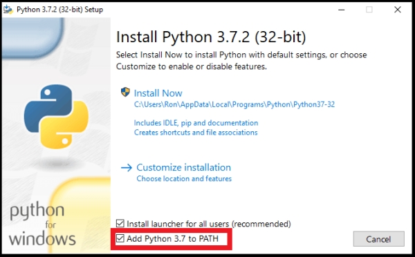
Anyway, If you don’t have python installed install latest version from here. While installing make sure you have checked the box that says ‘add python to environment variable path’.
Okay then I opened terminal and installed two libraries, Pyserial and screen-brightness-control using these commands ($ signs are to denote them as terminal command, copy without them)–
$ pip install pyserial
$ pip install screen-brightness-control<br>
After installing that I wrote the whole code. But let’s break it to you guys a bit.
Here I import libraries to use them. ‘serial.tools.list_ports’ is needed to detect Arduino board automatically.
# import necessary libraries
import serial                                     # for serial communication
import serial.tools.list_ports                    # to get Arduino port automatically
import screen_brightness_control as brightness    # to control brightness
Then I declare buad rate and port no. Port is automatically detected so I kept it as empty string. But for my board, buad rate is 9600
BUAD_RATE = 9600                                  # Pro Micro's buad rate is 9600
PORT      = ""
This section gets usb ports automatically and tries to connect with Arduino
# get sender device port automatically
serial_ports = list(serial.tools.list_ports.comports())  # get list of ports
for s_port in serial_ports:                              # iterate through all ports
    if 'Arduino Micro' in s_port.description:            # look for Pro Micro board
        PORT = str(s_port[0])                            # select first found board and
        break                                            # proceed

# connect with sender device
sender = serial.Serial(PORT, BUAD_RATE)<br>
This is the function that converts Arduino data (from 0 to 1024) into %data – from 0 to 100. It’s called mapping. Python map function does something else, so I had to write it (took some help from internet though).
def map_value(value, in_min=0, in_max=1024, out_min=0, out_max=100):
    """ To map values. Arduio sends values from 0 to 1024. My goal
    is to make them in between 0 to 100."""
    return int((value - in_min) * (out_max - out_min) / (in_max - in_min) + out_min)
The rest of the code just makes sure that brightness stays at light intensity level
# mainloop
while 1:
    # convert byte data into string then integer
    sensor_value = int(sender.readline().decode("utf-8"))  # get data
    final_value = map_value(value=sensor_value)            # map value (brightness in percentage)
    #print(sensor_value)
    print(final_value)
    brightness.set_brightness(final_value)                 # set brightness

# close port properly so that others can use it
sender.close()<br>
Anyway, it’s always best to close something you opened after use, whether it’s conversation or port.
Now, I opened my favorite python editor and ran the program. Download the full program from github.
""" Computer Hack!
    Brightness Controller

    (C) License: GPL3-General Public License

    author: ashraf minhaj
    mail  : [email protected]
"""

""" libraries -
$ pip install pyserial
$ pip install screen-brightness-control
"""

# import necessary libraries
import serial                                     # for serial communication
import serial.tools.list_ports                    # to get Arduino port automatically
import screen_brightness_control as brightness    # to control brightness

# device buadrate (bit per second)
# (change buadrate according to your need)
BUAD_RATE = 9600                                  # Pro Micro's buad rate is 9600
PORT      = ""

# get sender device port automatically
serial_ports = list(serial.tools.list_ports.comports())  # get list of ports
for s_port in serial_ports:                              # iterate through all ports
    if 'Arduino Micro' in s_port.description:            # look for Pro Micro board
        PORT = str(s_port[0])                            # select first found board and
        break                                            # proceed

# connect with sender device
sender = serial.Serial(PORT, BUAD_RATE)

def map_value(value, in_min=0, in_max=1024, out_min=0, out_max=100):
    """ To map values. Arduio sends values from 0 to 1024. My goal
    is to make them in between 0 to 100."""
    return int((value - in_min) * (out_max - out_min) / (in_max - in_min) + out_min)

# mainloop
while 1:
    # convert byte data into string then integer
    sensor_value = int(sender.readline().decode("utf-8"))  # get data
    final_value = map_value(value=sensor_value)            # map value (brightness in percentage)
    #print(sensor_value)
    print(final_value)
    brightness.set_brightness(final_value)                 # set brightness

# close port properly so that others can use it
sender.close()
Source: Hack Computer to Make It Smart!