Summary of Make Arduino Based Home Automation Part-1 Using ARDUINO UNO R3
This article introduces Part 1 of an Arduino-based home automation project using the Arduino UNO R3. It details a wired system where three pushbuttons control two lamps and a fan via relays, with status updates displayed on a 20x4 LCD screen. The tutorial includes the full C++ code, pin definitions, and a step-by-step algorithm explaining how button inputs toggle relay outputs. A second part involving RF wireless communication is mentioned but not covered in this text.
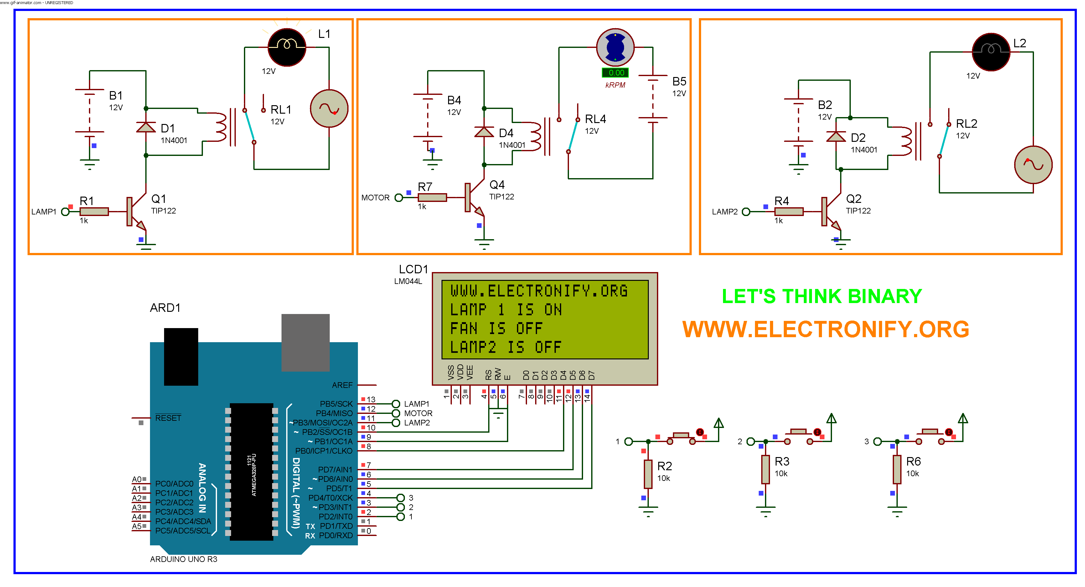
Parts used in the Arduino Based Home Automation Project:
- Arduino UNO R3
- Liquid Crystal Display (LCD) 20x4
- Pushbutton switches (3 units)
- Relay modules (3 units)
- Lamps (2 units)
- Fan (Motor)
Hello every one welcome back . In this project tutorial I will show you how to make arduino based home automation , this means you can control all of your home appliences and devices using a single microcontroller . This Tutorial is divided into two part . In second part of this tutorial I will use RF communication module for wireless home automation . Let us first upload this program to the circuit above and observe the result . The circuit with code can be download from this link wireless home automation . And description is shown below the code .
Make Arduino Based Home Automation Part-1 Using ARDUINO UNO R3 (Code)
/*created by Prasant Bhatt

www.facebook.com/elefy

you can do whatever you want with this code

*/

#include `

LiquidCrystal lcd(10, 9, 8, 7, 6, 5);

// constants won't change. They're used here to

// set pin numbers:

const int buttonPin1 = 2;     // the number of the pushbutton pin

const int buttonPin2 = 3;

const int buttonPin3 = 4;

const int relayPin1 = 13;      // the number of the relay pin

const int relayPin2 = 12 ;

const int relayPin3 = 11;

// variables will change:

int buttonState1 = 0;         // variable for reading the pushbutton status

int buttonState2 = 0;

int buttonState3 = 0;

void setup() {

// initialize the relay pins as an output:

pinMode(relayPin1, OUTPUT);

pinMode(relayPin2,OUTPUT);

pinMode(relayPin3,OUTPUT);

// initialize the pushbutton pin as an input:

pinMode(buttonPin1, INPUT);

pinMode(buttonPin2, INPUT);

pinMode(buttonPin3, INPUT);

lcd.begin (20, 4);

lcd.clear ();

lcd.setCursor (0, 0);

lcd.print ("WWW.ELECTRONIFY.ORG");

}

void loop(){

// read the state of the pushbutton value:

buttonState1 = digitalRead(buttonPin1);

buttonState2=digitalRead(buttonPin2);

buttonState3=digitalRead(buttonPin3);

// check if the pushbutton is pressed.

// if it is, the buttonState is HIGH:

if (buttonState1 == HIGH) {

// turn Lamp on:

digitalWrite(relayPin1, HIGH);

lcd.setCursor (0, 1);

lcd.print ("LAMP 1 IS ON ");

}

else {

// turn Lamp off:

digitalWrite(relayPin1, LOW);

lcd.setCursor (0, 1);

lcd.print ("LAMP 1 IS OFF ");

}

if(buttonState2==HIGH){

digitalWrite(relayPin2,HIGH);

lcd.setCursor (0, 2);

lcd.print ("FAN IS ON ");

}

else{

digitalWrite(relayPin2,LOW);

lcd.setCursor (0, 2);

lcd.print ("FAN IS OFF ");

}

if(buttonState3==HIGH){

digitalWrite(relayPin3,HIGH);

lcd.setCursor (0, 3);

lcd.print ("LAMP 2 IS ON  ");

}

else{

digitalWrite(relayPin3,LOW);

lcd.setCursor (0, 3);

lcd.print ("LAMP2 IS OFF ");

}

}
Make Arduino Based Home Automation Part-1 Using ARDUINO UNO R3 (Schematic Diagram)
Description
The code is very simple to understand , the step by step algorithm is shown below
- first include liquidCrystal header file and initialize LCD using
- after that define pins for buttons and relay
- initialize button state 0 initially
- inside the setup define the button pin as input (because we are taking input from buttons ) and relay pins for output
- display ELECTRONIFY.ORG on first line of liquid crystal display
- inside infinite loop , determine whether button are pressed or not using digitalRead function
- if 1st button is pressed then 1st lamp is on and that condition is displayed on liquid crystal display
- similarly if second button goes high ( ie pressed ) then motor is on and that condition is displayed
- similar condition for third button and 2nd lamp
that’s it . In second part we will discuss about how to make wireless arduino based home automation , Keep sharing and stay tuned . If you have any question about this project please comment below .
Make Arduino Based Home Automation Part-2 (wireless) Using ARDUINO UNO R3
- What components are required for the first part of this home automation project?
The project uses an Arduino UNO R3, a 20x4 LCD, three pushbuttons, three relays, two lamps, and a fan. - How does the system display the status of the devices?
The system displays the status on the liquid crystal display by printing messages like LAMP 1 IS ON or FAN IS OFF based on button input. - Can I control multiple appliances with a single microcontroller in this setup?
Yes, the tutorial demonstrates controlling all home appliances and devices using a single microcontroller. - What function is used to read the state of the pushbuttons?
The digitalRead function is used inside the infinite loop to determine whether buttons are pressed or not. - Which pins are assigned to the relay modules in the code?
Relay pins 1, 2, and 3 are assigned to digital pins 13, 12, and 11 respectively. - Does this tutorial cover wireless control methods?
No, this text covers only the wired version; wireless control using an RF module is discussed in the second part of the tutorial. - What website is displayed on the first line of the LCD during initialization?
The text ELECTRONIFY.ORG is displayed on the first line of the liquid crystal display when the setup runs.