Summary of How to Make Arduino Based Collision Detection Warning System
This article outlines a step-by-step guide to building an Arduino-based collision detection warning system for vehicles. It details the required hardware components, their specific pin connections to the Arduino microcontroller, and the setup process using the Arduino IDE. The system utilizes an ultrasonic sensor to detect obstacles and triggers visual (LEDs) and audio (buzzer) warnings to alert the driver and prevent accidents.
Parts used in the Arduino Based Collision Detection Warning System:
- Computer
- Arduino Micro-controller
- HR SC-04 Ultrasonic Sensor
- Piezo Buzzer
- Red LED
- Blue LED
- Jumper Wires
- USB Data Cable
This is arduino based collision detection warning system. This kind of system is fastest growing safety feature in automotive industries. Such system enables vehicles to identify the chances of collision and give visual and audio warning to driver. So that driver can take necessary action to avoid collision. This project idea is based on arduino controller and the whole system will give you very good understanding that how this system works. The step by step method is explained so that you can make this system. The hardware connection, pin information and arduino program is explained clearly.
Step 1: Items and Material Required
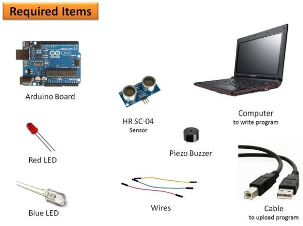
Please gather the following items
- Computer :- This is required to write program and flash program to controller. Also you need to install arduino IDE which is available free at arduino website download section.
- Controller :- I used arduino micro-controller. This you can get at online seller like amazon etc.
- Sensor :- I used HR SC-04 ultrasonic sensor.
- Piezo Buzzer :- I used piezo buzzer to make audio warning.
- LED :- There is two type of LED i used to which is red LED and blue LED.
- Wires :- There were jumper wires required to make hardware connections. You need to take all type of jumper wires like both end male, both end female and one end male another end female type.
Step 2: Connect All Hardwares
The hardware you gather in first step, now connect all them to controller through wires.
Sensor to controller pin information :-
Sensor has four pins VCC, Trig, Echo and GND. Connect…
VCC pin to 5V on controller
GND pin to GND on controller
Trig pin to pin-7 on controller
Echo pin to pin-4 on controller
Piezo Buzzer to controller pin information :-
Piezo buzzer has two pin.
Connect one pin to pin-10 on controller
Connect another pin to GND on controller
Red LED to controller pin information :-
Red LED has two pin.
Connect one pin to pin-2 on controller
Connect another pin to GND on controller
Red LED to controller pin information :-
Red LED has two pin.
Connect one pin to pin-13 on controller
Connect another pin to GND on controller
Controller to Computer connection information :-
You have USB data cable that you got while buying arduino. By this data cable you connect computer to arduino board.Now launch the arduino IDE. After connecting to computer you must have to select board and port from menu.
please see the attached screen shot for the help.
Read More: Arduino Based Collision Detection Warning System
- What is the primary function of this system?
The system enables vehicles to identify chances of collision and provide visual and audio warnings to the driver. - Which controller is used in this project?
An Arduino micro-controller is used as the central controller for the system. - How do you connect the Trig pin of the sensor?
The Trig pin connects to pin-7 on the controller. - What pins are used for the Piezo Buzzer?
One pin connects to pin-10 on the controller and the other to GND. - Where should the Red LED be connected?
The Red LED connects to pin-2 on the controller with the other end at GND. - Where should the Blue LED be connected?
The Blue LED connects to pin-13 on the controller with the other end at GND. - How does the computer communicate with the Arduino?
A USB data cable is used to connect the computer to the Arduino board. - What software is required to flash the program?
You need to install the Arduino IDE available free from the Arduino website download section.