Summary of Magic Dome
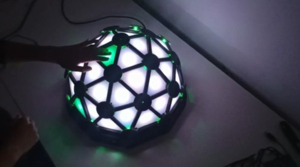
This article details a university final project creating an interactive geodesic LED dome using plywood, PLA, and Arduino. The dome features 40 triangular panels equipped with NeoPixel LEDs and IR sensors for touch interaction. It includes four operating modes: Creative, Piano, Music, and Simon Game. The project emphasizes the challenges of sensor calibration and recommends capacitive or resistive alternatives in future designs.
Parts used in the Interactive Geodesic LED Dome:
- NeoPixel Digital RGB LED Strip
- IR sensors
- 470 Ohm resistor
- 10K Ohm resistor
- 47K Ohm potentiometer
- NPN transistor
- 8-channel 74LS151 multiplexer
- Buzzer
- 15W power supply (5V 3A)
- Arduino UNO
- Prototype boards
- Cables
- DIP socket
- Push buttons
- Plywood
- PLA filament
- Soldering iron, flux, and tin
- Spray paint
- Multimeter
- Electric jigsaw machine
- Drill
- Sandpaper
- Wood glue
- Screws
- Silicone
Francisca Molero Luque, Dolores Martín Cabrera and Laura Mejía Ospina, students of ‘Creative Electronics’, a Beng Electronics Engineering module at the University of Málaga, School of Telecommunications. We decide to make as final project a derivation of Interactive Geodesic LED Dome.
Supplies
– NeoPixel Digital RGB LED Strip
– IR sensors
– 470 Ohm and 10K Ohm resistor
– 47K Ohm potentiometer
– NPN transistor
– 8-channel 74LS151
– Buzzer
– 15W power supply
– Arduino UNO
– Prototype boards
– Cables
– DIP socket
– Push buttons
– Plywood
– PLA
– Soldering iron, flux and tin
– Spray paint
– Multimeter
– Electric jigsaw machine
– Drill
– Sandpaper
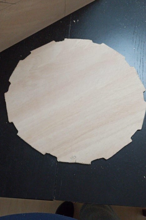
Step 1: Dome Design
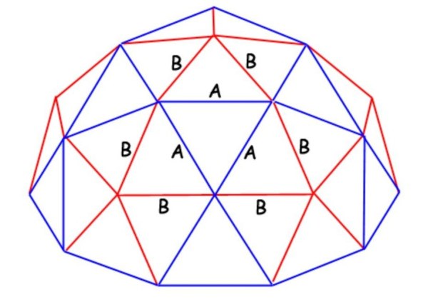
Initially, in order to get a dome composed by 40 triangles, there are two crucial different types of triangles. The measurements of each wooden triangle are, likewise, calculated within the following program: Desert Domes
Moreover, 10 triangles with measurements AAA in which A = 9.3 cm and 30 triangles with measurements BBA where B = 8.2 cm will be needed. On this way, the tips of both the plywood and the PLA triangles have to be trimmed in order to make them fit properly.
In addition, it is necessary to make two holes at the ends of the wooden triangles to enable passing the Vcc, GND and the data cables of each led.
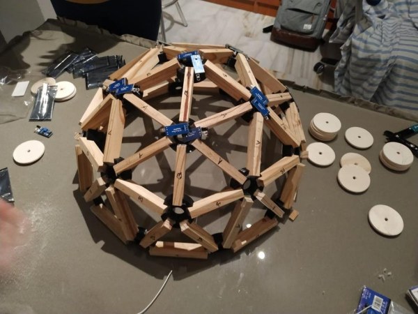
Regarding the support of the dome, the same measurements will be used. Therefore, 35 pieces of wood measuring 9.3 cm (measurement A) and 30 pieces of wood measuring 8.2 cm (measurement B) will be required.
All pieces of wood are 1.9 cm high and 1.2 cm wide. Hence, we will have 35 pieces of wood of 9.3 x 1.2 x 1.9 cm and 30 pieces of wood of 8.2 x 1.2 x 1.9 cm.
However, as shown below, for this support 3 types of connectors will
be required:
– 10 units x 4-connector.
– 6 units x 5-connector.
– 10 units x 6-connector.
– 10 triangles x AAA.
– 30 triangles: x BBA (these BBA type triangles are thin enough to be cut with scissors and then adapted to the desired size of this dome).
Nevertheless, the 3D printer .stl files for each PLA triangle and the
three types of connectors are the following:
Step 2: Sensor Design and Implementation
Beforehand, IR sensors were used and they were glued (in pairs or individually) to the wooden circles. Next, these have previously been cut from a wooden triplex with a drill and a cup saw. Each pair of the sensors have a different position depending on their location within the dome.
The sensors have three outputs: OUT, VCC and GND.
– VCC and GND are common to all from the power supply.
– OUT the digital output of each sensor.
The metal pins were cut off to solder the cables. Moreover, it is important to list the output of each sensor and calibrate it in a similar environment for its future use, since these are sensitive to light (they do not work properly with natural light); and with the final power supply, since a change in VCC generates changes in its sensitivity as well. Calibration is performed by adjusting the potentiometer which is included in each sensor until reaching the desired distance.
Prior to assembly, each group of eight sensors has been tested on a breadboard.
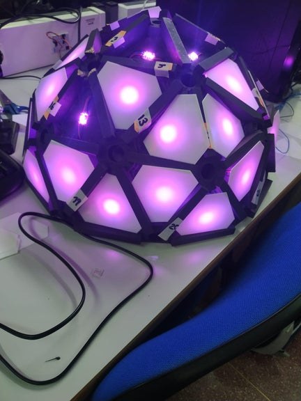
Step 3: LEDs Mounting
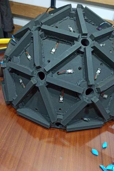
Firstly, 40 LEDs were cut from a strip of addressable LEDs (Neopixel) and have been placed within each triangle of the dome. It is important to add that the background of the triangle is light coloured, for instance; white. This will help not to lose light from the LEDs, and the color will also fade much better when the PLA triangle is placed on top. It is also crucial to make sure that, when placing the PLA triangles on the LEDs, the peaks of the triangles are making contact with the connectors to avoid leaving them directly upon the LED. Besides, this will also add more color to each triangle.
Regarding the connection of the LEDs, it is necessary to weld a cable and data to the Vcc, the GND and also to the 40 LEDs in order to connect it with the next LED on the dome. The last led of the dome will carry its Vcc, GND and data connections to the corresponding pin of the Arduino UNO. Although, it will be necessary to previously place a 470 ohm protection resistor between the Arduino and the data cable of the led strip. In addition, a 1000 uF capacitor placed between GND and Vcc will also be necessary to protect the LEDs.
All in all, these connections are detailed in the images within this step.
Step 4: Electronics and Sensor Multiplexing
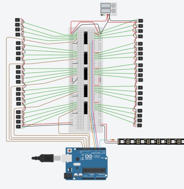
It is crucial to use multiplexing since there are not enough pins within Arduino Uno. Therefore, each group of eight sensors is multiplexed with an integrated 8-channel 74LS151. An output from each one of them will come by only to be connected to a digital port of Arduino Uno; 3-7 pins as shown in the image. The control signals are generated by the Arduino Uno; in this case, for 40 sensors there are 3 control signals corresponding to pins 8, 9 and 10.
The multiplexing tests were, furthermore, made on a breadboard, and after that, all the connections and components were soldered to the propotype boards.
As shown in the pictures, there is a complete multiplexing assembly for all 40 sensors.
Step 5: Dome Base
For the base of the dome, a decagon-shaped box was built and it has two push buttons; the switch power input and the Arduino input.
Regarding the construction, a wooden triplex has been used. Moreover, all parts have been cut with an electric jigsaw machine, then sanded and painted. The pushbuttons have been perforated with a drill.
As for the source and the input of the Arduino, a drill was used instead. The sides were glued both from the bottom side and to each other with extra strong wood glue, while the top cover is secured with screws to ease its maintenance.
Thus, inside this dome base, the speaker, the Arduino UNO, the power supply and all the wiring of the dome are fixed with silicone.
Step 6: Power Supply and Speaker
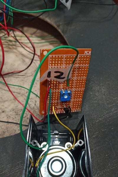
The power supply provides 5V and 3A; It is connected to a plug with switch and a 4A 250V fuse, (for information on how to connect the switch: Socket with switch and fuse). Additionally, V + and V- outputs of the source provide power for the entire electrical circuit, each connected to Vin and GND respectively.
The loudspeaker consists of a buzzer, with a small amplification stage; (see pictures of schematic), the output is connected to pin 12 of the Arduino.
The power supply and the Arduino UNO are attached to the base of the dome with casings printed with PLA. As shown below, the .stl files can be found following this:
Step 7: Programming the Dome
Although there are actually as many programs as imagination allows, these are some that will be left as implemented:
– Creative mode: It allows painting in any color by touching each triangle.
– Piano mode: Each level of the dome belongs to musical notes. As a result, a respective sound will be made by a note every time a triangle is touched.
– Music mode: While a melody is playing, the dome lights up randomly.
– Simon Game: The game’s programming is based on the following video; Simon say
The buttons have been programmed to switch modes within the example on a state machine.
We have uploaded each of our programming to the GitHub digital repository.
Step 8: Design Recommendations
Here are some aspects to avoid in order to both facilitate and speed up the movement and avoid possible problems:
– IR sensors are not recommended at all, since they generate many calibration problems and vary from one environment to another, it is very tedious to recalibrate them due to their location in the structure. Another disadvantage would be their size, which is inconvenient. Instead, it is recommended to use capacitive, resistive sensors or any other type of tactile sensor.
– Being this a manual assembly, the holes formed by the wood are not all exactly the same. For the PLA triangles to fit perfectly, 40 would have to be designed and it is better to directly cut them to length.
– It is crucial to state the importance of taking into account the quality of the materials when buying them in order to avoid future failures (cables, sensors, etc.).
Source: Magic Dome
- How many triangles are required for the dome design?
The design requires 40 triangles in total, consisting of 10 type AAA and 30 type BBA. - Can IR sensors be used directly without calibration?
No, IR sensors must be calibrated because they are sensitive to light and changes in VCC affect their sensitivity. - What is the best way to connect the LEDs to the next one?
You must weld a cable and data line to the Vcc, GND, and data connections of each LED to link them sequentially. - Does the Arduino Uno have enough pins for all sensors?
No, multiplexing is crucial because there are not enough pins on the Arduino Uno, so an 8-channel 74LS151 is used. - What material is recommended instead of IR sensors?
The authors recommend using capacitive, resistive, or other tactile sensors due to the calibration issues with IR sensors. - How should the PLA triangles be prepared for assembly?
The tips of the PLA triangles must be trimmed to fit properly with the wooden triangles and connectors. - What protection components are needed for the LED strip?
A 470 ohm resistor is needed between the Arduino and data cable, and a 1000 uF capacitor is needed between GND and Vcc. - What modes are implemented in the dome programming?
The implemented modes are Creative mode, Piano mode, Music mode, and Simon Game. - How are the push buttons utilized in the base?
Two push buttons are installed in the decagon-shaped base to switch power input and change programming modes. - Why was a 15W power supply selected for this project?
The power supply provides 5V and 3A to ensure the entire electrical circuit, including the LEDs and sensors, operates correctly.