Summary of LPG sensor using arduino
This article details an Arduino-based LPG safety system using an MQ2 sensor to detect flammable gases like propane and butane. The circuit monitors gas concentration by measuring resistance changes in the sensor, converting analog voltage to digital values via ADC, and calculating the percentage of gas present. When levels exceed a threshold, the system triggers an alarm and activates a relay cutoff.
Parts used in the LPG sensor using Arduino with alarm and cutoff:
- Arduino
- MQ2 gas sensor
- Relay
- Alarm
- Load resistor
- Heating element
LPG sensor using Arduino with alarm and cutoff.
A simple LPG sensor using Arduino is shown in this article. This circuit indicates the amount of LPG in the air. The circuit sounds an alarm and trips a relay when the concentration is above a predetermined level. MQ2 is the gas sensor used in this project. MQ2 is an SnO2 based gas sensor which can sense gases like methane, propane, butane, alcohol, smoke, hydrogen etc. Since LPG primarily contains propane and butane, MQ2 sensor can be used for sensing LPG. The figure below shows the schematic and arrangement of an MQ2 gas sensor.
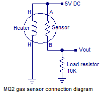
MQ2 sensor senses the flammable gases by the increase in temperature when they are oxidized by the heating element. Consider the figure given above. If there is any flammable gas present in the sample , the oxidization of the same gas results in increased temperature and the resistance of the sensor resistor will drop. That means more current will flow through the load resistor and so the voltage across it will shoot up.
At normal conditions(no LPG in the air), the sensor resistor will be very high around 850K . So the voltage drop Vout across the load resistor will be around zero. When the sensor is fully exposed to LPG the sensor resistance drops to around 800 ohms and the voltage drop across the load resistance will be around 4.62 volts. After conversion by the ADC, the digital equivalent of 4.62 volt will be 948 and it is stored in the variable “d” (refer the program ). Figure below shows a graph plotted from the observed parameters.
Actually the graph may not be a straight line. But here we have to assume it to be a straight line because it is not possible to simulate LPG concentrations other than 0% and 100% with our limited lab facilities. For accurate calibration of the sensor, we need some means to know the precise concentration of the gas in the given environment. Anyway what we have is somewhat enough for our purpose.
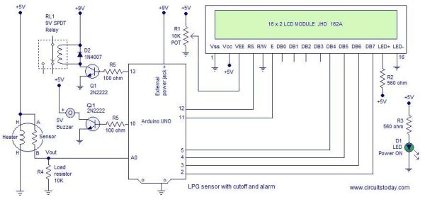
The concentration percentage for a given digital output of the ADC can be determined using the following equation. p=d/9.48 where d is the digital output of the ADC and p is the percentage. The equation is obtained by finding the equation of the above graph in the general form y=mx+c. Where m is the slope and c is the y intercept. The full circuit diagram of the LPG sensor using Arduino is shown below.
For more detail: LPG sensor using Arduino
- What gas sensor is used in this project?
The project uses the MQ2 sensor which is an SnO2 based gas sensor. - How does the MQ2 sensor detect flammable gases?
The sensor detects gases by the increase in temperature when they are oxidized by the heating element. - What happens to the sensor resistance when exposed to LPG?
The sensor resistance drops from around 850K to around 800 ohms when fully exposed to LPG. - How is the gas concentration percentage calculated?
The percentage is determined using the equation p equals d divided by 9.48 where d is the digital output. - Does the graph of observed parameters appear as a straight line?
The actual graph may not be a straight line but it is assumed to be one for simulation purposes. - What occurs when the gas concentration exceeds a predetermined level?
The circuit sounds an alarm and trips a relay to cut off the supply. - Why is accurate calibration difficult in this setup?
Accurate calibration requires knowing the precise concentration of gas which is hard to simulate with limited lab facilities. - What type of gases can the MQ2 sensor sense?
The sensor can sense methane, propane, butane, alcohol, smoke, hydrogen, and LPG.