Summary of Line Frequency Meter Based On Reciprocal Counting
This article details a line frequency meter designed for precise power grid management, achieving 0.01Hz resolution using the reciprocal counting method. Unlike standard counters, this system eliminates zero-crossing errors by measuring integral cycles of the input signal against a reference clock. The project utilizes an Arduino Uno platform to count 50 input cycles while simultaneously timing them with a software-generated reference, calculating frequency via a simple reciprocal formula.
Parts used in the Line Frequency Meter:
- Arduino Uno
- Step-down transformer (230V primary to 12V-0-12V, 300mA secondary)
- Transistor BC547
- Tone() function (software component)
- Four-digit display counter (ICOUNT or similar IC like ICL7217/NS74C926)

Precise measurement of line signal frequency is very important in many applications, especially in the management of power grid systems. Tasks like calibration of governors of engines that run generators in power plants need a resolution up to 0.01Hz. Frequency is also an important parameter in load sharing among several power plants in the grid. Presented here is a line frequency meter, that does it for you.
Line frequency meter concept
When the required resolution of the displayed frequency is 1Hz, the instrument becomes simple. Direct frequency counting is one of the many possible methods as shown in Fig. 1.
Block diagram for direct frequency counting
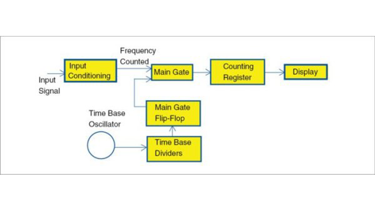
However, when the resolution required is other than 1Hz, like, say, 0.1Hz or 0.01Hz, value of frequency is obtained from its period. Period is measured in microseconds and frequency is calculated from it. But this method suffers from errors caused by zero-crossing detectors.
In Fig. 2, input conditioning is mainly a zero-crossing detector that produces a pulse for each zero crossing of the sine wave. But here, errors can be caused by comparators whose threshold value may change due to temperature.
Block diagram for period measurement
Also, hysteresis present in the comparator can cause detection errors. Fig. 3 shows the cause of error in the measurement of the period of a signal.
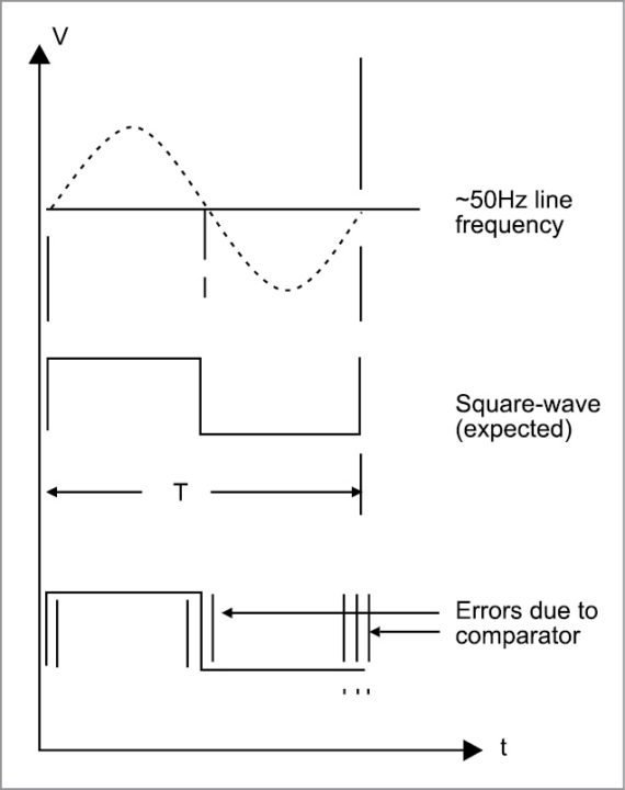
Zero-crossing errors caused by comparators
Reciprocal counter is a class of counter that makes a period measurement on input signal. But it does not use a single- or multi-period counter. Instead, it uses two counters called event and time. Value of frequency can be displayed directly by taking the reciprocal of the period measured as shown in Fig. 4.
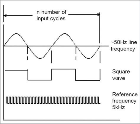
Diagram showing line frequency waveform and reference signal
Superiority of the reciprocal counting method over other two methods is given below:
1. Integral cycle of input signal cycles is used so that ±1 quantisation error is eliminated. This prevents comparator errors from affecting accuracy.
2. Higher resolution is obtained without a long measuring time.
Principle of operation
A generalised frequency meter with reciprocal counting is shown in Fig. 5.
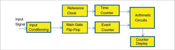
Block diagram of a general frequency meter with reciprocal counting
An exact number of input cycles are counted in event counter and, simultaneously, the reference clock is counted in time counter for the same duration.
An equation can be written as:
Ns x Ts=Nr x Tr
where Ns is the number of cycles of the input frequency (50 counts in this case) and Ts is the period of the input signal. Nr is the number of cycles of the reference frequency counted within this time and Tr is the period of the reference clock (0.2 milliseconds or 0.2ms in this case).
Frequency of signal is given by:
Fs=1/Ts=Ns/(Nr x Tr)
=50/(Nr x 0.2ms)=250000/Nr
If line frequency is exactly 50Hz, this equation will give:
Fs = (250000/5000) = 50
That is, to obtain a resolution of 0.01Hz, value in the display will be 50.00.
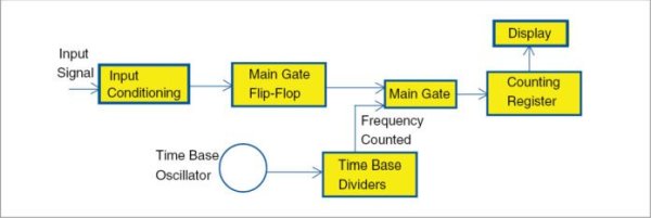
Arduino Uno is an excellent platform for the measurement of line frequency using the reciprocal counting method. A simplified block diagram of the line-frequency meter is shown in Fig. 6.
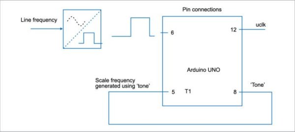
Simplified block diagram of the line frequency meter
In this figure, line-voltage sine-wave is converted into a square wave of TTL levels using only a transistor. This is sufficient because the event counter counts only integral cycles and that eliminates zero-crossing errors. This square wave is applied to port pin 6 of Arduino Uno.
Square-wave cycles are counted by the software and the event counter. Clock frequency for the time counter is obtained from Arduino itself by the use of Tone() function in the Arduino code as explained in software section. This signal is applied to counter T1.
1. Event counter software counts exactly 50 cycles of the input signal.
2. Time counter simultaneously counts the number of reference pulses.
3. A simple reciprocal calculation then finds the frequency.
A counter similar to the circuits based on ICL7217 or NS74C926 can be used as a four-digit display for Arduino Uno (Fig. 7). For example, if 1234 has to be displayed, all that is needed is to send 1234 clock pulses. But these counters (7217 and the like) require three signals: reset, latch and clock. That will take three pins of Arduino.
Note
A special counter named ICOUNT is available from a manufacturer in Madurai, Tamil Nadu. This counter requires only one port pin from Arduino. Reset and latch signals are automatically generated by ICOUNT. The number to be displayed is transferred from any available output port of Arduino as a train of pulses. When pulses stop to arrive, the display is updated.
Circuit and working
Circuit diagram of the line-frequency meter with reciprocal counting is shown in Fig. 7. A 230V primary to 12V-0-12V, 300mA secondary step-down transformer (X1) is used for the power supply input and to get a signal to drive transistor BC547 (T1) that provides a square-wave output corresponding to line-frequency input.
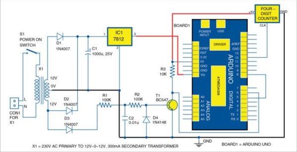
Circuit diagram of the line frequency meter with reciprocal counting
Read More Detail :Line Frequency Meter Based On Reciprocal Counting
- How does the reciprocal counting method improve accuracy?
It uses integral cycles of the input signal to eliminate ±1 quantisation error and prevent comparator errors from affecting accuracy. - What problem do zero-crossing detectors cause in period measurement?
Errors can be caused by comparators whose threshold values change due to temperature or hysteresis present in the comparator. - How is the square wave generated from the line voltage?
A 230V sine-wave is converted into a TTL level square wave using only a transistor driven by a step-down transformer. - What specific number of input cycles does the event counter measure?
The event counter software counts exactly 50 cycles of the input signal. - Which Arduino function provides the clock frequency for the time counter?
The Tone() function in the Arduino code is used to obtain the clock frequency for the time counter. - How does the special ICOUNT counter differ from standard counters?
The ICOUNT requires only one port pin from the Arduino because it automatically generates reset and latch signals. - What is the reference clock period used in the example calculation?
The reference clock period (Tr) is 0.2 milliseconds or 0.2ms. - Why is the direct frequency counting method insufficient for high resolution?
Direct counting is simple for 1Hz resolution but fails to provide higher resolutions like 0.1Hz or 0.01Hz without significant errors.