A line follower robot using 8051 microcontroller is already published here and this time the same thing is done using arduino. This line follower robot is basically designed to follow a black line on a white surface. Any way the same project can be used to follow the opposite configuration with appropriate changes in the software. The entire hardware of this simple line follower robot using arduino can be divided into three parts. The sensor, arduino board and the motor driver circuit. Lets have a look at the sensor first.
 Sensor.
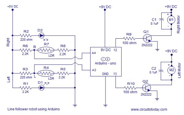
The sensor consists of two LED/LDR pairs with appropriate current limiting resistors. The resistance of an LDR is inversely proportional to the intensity of the light falling on it.
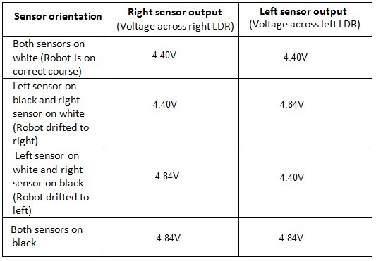
Resistors R1 and R2 limits the current through the LEDs. Resistors R6, R8, R3,and R5 forms individual voltage divider networks in conjunction with the corresponding LDRs. When the sensor is correctly aligned, both LED/LDR pairs will over the white surface. In this condition sufficient amount of light gets reflected back to the LDRs and so their resistance will be low. So the voltage dropped across the LDR will be low. When the robot is drifted to one side , the sensor in the opposite side falls over the black line and the intensity of light reflected back to the corresponding LDR will be low. As a result the resistance of the LDR shoots up and the voltage dropped across it will be high. The voltages dropped across the right and left LDRs (nodes marked R and L in the above circuit) are given as input to the analog input pins A4 and A3 of the Arduino board. Right and left sensor outputs observed while testing the above circuit is shown in the table below.
Arduino uno board.
The arduino board has to be programmed to keep the robot in correct path. This is done by reading the left and right sensor outputs and switching the left and right motors appropriately. Output of the right sensor is connected to the analog input A4 of the arduino and output of the left sensor is connected to the analog input A3 of the arduino. The voltage range that can be applied to a particular analog input of the arduino is 0 to 5V. This range can be converted into a digital value between 0 and 1023 using analogRead () command. For example if 3V is applied to A3, the following code will return 3/(5/1023) which is equal to 613 in the variable leftValue.
int leftInput = A3;
int leftValue=0;
void loop ()
{
leftValue = analogRead (leftInput);
{
From the above table you can see that the voltage across a particular LDR will be 4.4V when it on white and 4.84V when it is on black. The digital equivalent of 4.4V will be 900 and that of 4.84V will be 990 as per the above scheme. The median of these two values is 945 and it is set as the reference point for the program to check the orientation of the sensor module.
The program identifies the position of the sensor module by comparing the sensor readings with the reference point that is 945. If the reading of a particular sensor is greater than 945 the program can assume that the particular sensor is above black. If the reading of a particular sensor is less than 945 then it is assumed that the particular sensor is above white. If both sensor readings are less than 945 then it means both sensors are on white. If both sensor readings are above 945 it is assumed that both sensors are above black (the same thing happens if we lift the robot off the track). Based on the above four conditions, the program appropriately switches the left and right motors to keep the robot following the black line.
Motor driver.
The motor driver circuit is based on two NPN transistors Q1 and Q2. Each transistors are wired as a switch with a resistor at its base for limiting the base current. The motors are connected to the emitter terminal of the corresponding transistors. A 0.1uF capacitor is connected across each motor for by-passing the voltage spikes. Back emf and arcing of brushes are the main reason behind the voltage spikes. If these voltage spikes are not by-passed it may affect the Arduino side.
For more detail: Line Follower Robot using Arduino