
Summary of Light-Up Disco Table using Arduino
This article details a DIY project to build a battery-powered coffee table featuring customizable LED patterns controlled by an Arduino. The design includes an open-framed cube structure with embedded LEDs diffused through acrylic, allowing for a smooth surface without cords. It also suggests adapting the circuitry for existing tables.
Parts used in the Light-Up Disco Table:
- Arduino Mega
- 5x tricolor LED strips
- 8x AA batteries
- 8x AA battery holder
- Push button
- Power switch
- 10K ohm resistor
- Breadboard
- Misc wires, connectors, and soldering supplies
- Maple wood
- Plywood
- Wood screws
- Metal t-braces
- Metal l-brackets
- Acrylic (abrasion-resistant)
- Wood finish (Danish oil)
- Brushes and rags
- Acrylic adhesive
Every apartment needs awesome furniture, so why not make your own? This coffee table contains LED strips that light up into various customizable patterns and colors. The lights are controlled by an Arduino and a hidden button, and the entire thing is battery powered so there are no cords.
If you don’t want to make your own table, you can also use the same code and circuitry to modify an existing table.
Materials:
- Arduino Mega – RadioShack 276-127
- 5x tricolor LED strips – RadioShack 276-339
- 8x AA batteries – RadioShack 23-2212
- 8x AA battery holder – RadioShack 270-387
- Push button – RadioShack 275-644
- Power switch – RadioShack 5505076 (online only)
- 10K ohm resistor – RadioShack 271-1126
- Breadboard – RadioShack 276-149
- Misc wires, connectors, and soldering supplies
- Wood – for my table, maple and plywood
- Wood screws (I used all #8, of various lengths)
- Metal t-braces
- Metal l-brackets
- Acrylic (abrasion-resistant, since it is a table and will be used)
- Wood finish (I used Danish oil), brushes, and rags
- Acrylic adhesive
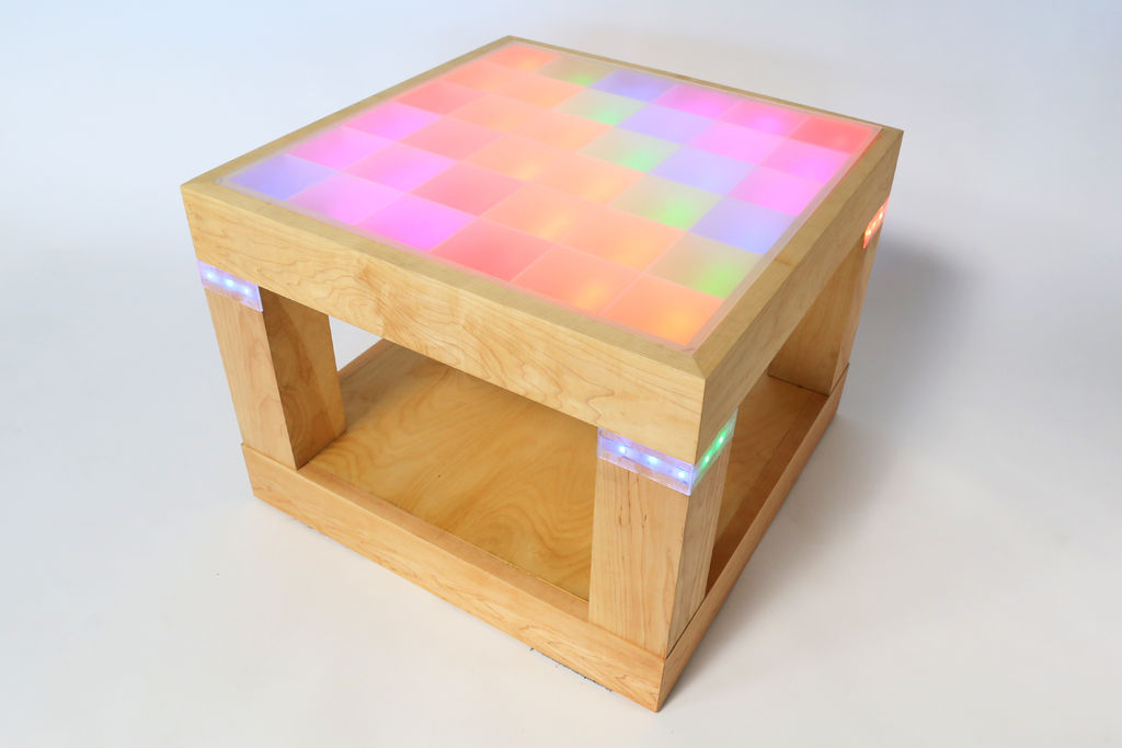
Step 1: Table Design
This was my first woodworking project using nice wood and “advanced” tools, so please do not consider me an expert. Rather than describing in detail how I made the table, I’ll give more of a broad overview of what I did*.
The design of the table is an open-framed cube, with space in the top for the electronics and additional LED strips around the legs. The lights are diffused through plastic which is embedded flush with the wood to create a smooth surface.
*Note that I did a few things in ways that were not ideal. In the instructions I will outline a better method for making the table than what I actually did. Generally, the changes involve cutting certain pieces all at the same time to ensure that they are the same length.
EDIT: I added the part files for the table. Note that they are Inventor files, not generic stls. (I don’t have Inventor anymore so I can’t open/convert them).
 LEDTable.zip2 MB
Step 2: Make the top and base frames
The top and base of the table are essentially open frames with various grooves cut out for joining and assembly.
For both of them, I started by jointing and planing lengths of maple to the thicknesses specified in the design. Next, I used the table saw to carefully cut out long notches from the edges of the parts. The base frame only has one groove, but the top frame has multiple. Make sure to check that your piece of plastic fits flush after you cut the groove it will sit in (you won’t be able to go back and make it deeper).
You should then miter all eight pieces to length using a jig (this is something that I did not do, so my top and base frames were slightly different sizes). Also cut grooves for adding splines (strips of wood) when you glue the frames together. With the top frame, make sure that you cut the grooves so the splines won’t be visible on the finished top surface (make sure they pass through the inner edge, where the plastic will sit and cover them).
Set all the pieces near their places and glue/clamp the frames together. Take care that the edges of the miters are touching and that the frames are sitting flush with the surface they are on. Once they are dry, trim away any part of the spline that is sticking above the surface of the frame.
Step 3: Cut and attach the inner frame
A thin plywood frame sits inside the top frame and acts as a connecting surface between the top frame and the legs, as well as a mounting surface for the electronics tray.
I started by cutting all my plywood strips to the same length and width on the table saw. Next, I marked and drilled holes near the edges so that later on I would be able to access the cables from the LEDs in the legs. I then cut the corners to 45 degree angles on the chop saw so the strips would fit neatly together as a frame. I routed a groove along the inside edge so the electronics tray would be able to sit flush with the frame’s surface. Finally, I attached the strips of the inner frame to the bottom of the top frame with wood glue and brads.
Step 4: Make the electronics tray
Most of the electronics for the table are mounted on a removable plywood tray underneath the top frame.The tray fits flush to the inner frame, with routed edges on all sides. After routing, I cut squares from all four corners of the tray so it could fit around the legs and be removed if I ever needed to access the electronics. Finally, I drilled holes for the power switch and control button.
Step 5: Make the legs
The legs are made of two pieces of planed maple (which face outwards) and two pieces of plywood (which face the inside of the table). I cut all the parts (both plywood and maple) for the legs at the same time, so I knew they were the same width and length.
Some of the LED strips are embedded in the maple, so I had to cut a deep groove using a dado blade on the table saw. I then used a normal blade to cut a space for the embedded plastic. Without moving the blade, I trimmed off a thin strip at the edge of the plywood pieces for where the edges of the plastic would lie. I did the same thing to create the raised step where the legs would attach to the underside of the top frame. Lastly, I cut the mitered long edges of the parts.
One of the shop staff taught me a useful trick for gluing together the legs, which was to hold the parts together using blue tape. Arrange the parts, then tightly connect the edges with strips of tape. Unfold the leg and apply glue to the joints. Refold the leg and seal the last corner before letting it dry. Since the tape holds everything in place, the corners are nicely flush without fighting with clamps.
Step 6: Finish the base
I cut another plywood square to fit on the top of the base frame and be connected with L-brackets. To install them I measured and marked the holes for the plywood panel, which I drilled half-way through with the drill press (I didn’t want to see the holes when I flipped the base right-side-up). Once the brackets were attached to the plywood, I hand drilled the pilot holes for connecting to the frame and put in the screws.
Step 7: Rout the edges
After the major components of the table were completed, I routed the external edges of the parts to keep them from splintering or chipping when I use the finished table.
Step 8: Sand and fill the parts
I sanded the all of the parts with 180 and 220 grit sandpapers and an orbital sander until smooth. I made sure to get as many of the interior edges as possible. After sanding, I filled gaps in the edges with small amounts of filler and sanded them flush again.
Step 9: Seal the parts
Once everything was sanded, I finished the parts with Watco Danish Oil to harden and seal the wood. I found it easiest to use a foam brush for applying the oil and a clean rag for removing it.
Step 10: Attach the electronics shelf
I didn’t want to worry about applying the oil around exposed metal parts, so I left the installation of the electronics shelf until after I applied the finish. I used T-brackets to attach it to the underside of the top frame. The holes in the shelf itself only go halfway through the wood to make sure the screws don’t poke out the top.
For more detail: Light-Up Disco Table using Arduino
- How is the table powered?
The entire table is battery powered using 8 AA batteries so there are no cords. - Can I modify an existing table instead of building one?
Yes, you can use the same code and circuitry to modify an existing table if you do not want to make your own. - What material is used for the light diffusion surface?
Abrasion-resistant acrylic plastic is embedded flush with the wood to create a smooth surface that diffuses the lights. - How are the legs glued together effectively?
You can hold the parts together using blue tape, apply glue to the joints, refold the leg, and seal the last corner before letting it dry. - When should the electronics shelf be attached?
The electronics shelf should be attached after applying the finish to avoid worrying about applying oil around exposed metal parts. - What type of wood was used for the table construction?
The author used maple for the visible faces and plywood for the inner frame and base components. - How are the grooves for the plastic checked during cutting?
You must check that the piece of plastic fits flush after cutting the groove because you will not be able to go back and make it deeper. - What tool is recommended for routing the edges?
An orbital sander is used for sanding, but a router is used to route the external edges to prevent splintering or chipping.
