Summary of LED Cube 8x8x8
This guide details how to build an 8x8x8 LED Cube, a 3D LED display with 512 LEDs controlled via multiplexing and persistence of vision to create dynamic 3D images. It covers theory, component selection, soldering techniques, power supply considerations, and software control using an ATmega32 microcontroller. The project involves creating a cube frame by soldering LED layers, expanding microcontroller IO via latches, and ensuring precise timing for flawless serial communication. Testing at every stage is emphasized to prevent defects.
Parts used in the 8x8x8 LED Cube Project:
- 512 LEDs (preferably 3mm diffused)
- 64 resistors (value per LED requirements)
- 1 or 2 large prototype PCBs with copper eyes
- 1x ATmega32 microcontroller (or ATmega16 compatible)
- 3 status LEDs (color/size optional)
- 3 resistors for status LEDs
- 8x 74HC574 latch ICs
- 16x PN2222 transistors
- 16x 1k ohm resistors
- 1x 74HC138 IC (3-to-8 line decoder)
- 1x Maxim MAX232 IC (RS232 interface)
- 1x 14.7456 MHz crystal oscillator
- 2x 22pF ceramic capacitors
- 16x 0.1uF ceramic capacitors
- 3x 1000uF electrolytic capacitors
- 3x 10uF electrolytic capacitors
- 1x 100uF electrolytic capacitor
- 8x 20-pin IC sockets
- 1x 40-pin IC socket
- 2x 16-pin IC socket
- 1x 2-pin screw terminal
- 1x 2-wire cable with plugs
- 9x 8-pin terminal pins
- 1x 4-pin right angle terminal pins
- 2x 16-pin ribbon cable connectors
- 1x 10-pin ribbon cable connector
- Ribbon cable (various lengths)
- 2x pushbuttons
- 2x ribbon cable plugs
- 9x 8-pin female header plugs
- Serial cable and 4-pin female header
- Piece of wood for jig/template and base
- Optional 8x pull-up resistors for layers
- 5V power supply (regulated, high current)
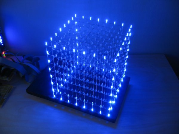
Create your own 8x8x8 LED Cube 3-dimensional display!
We believe this Instructable is the most comprehensive step-by-step guide to build an 8x8x8 LED Cube ever published on the intertubes. It will teach you everything from theory of operation, how to build the cube, to the inner workings of the software. We will take you through the software step by step, both the low level drivers/routines and how to create awesome animations. The software aspect of LED cubes is often overlooked, but a LED cube is only as awesome as the software it runs.
About halfway through the Instructable, you will actually have a fully functional LED cube. The remaining steps will show you how to create the software.
A video is worth a thousand words. I’ll just leave it up to this video to convince you that this is the next project you will be building:
I made this LED cube together with my friend chiller. The build took about 4 days from small scale prototyping to completed cube. Then another couple of hours to debug some faulty transistors.
The software is probably another 4-5 days of work combined.
Step 1: Skills required
At first glance this project might seem like an overly complex and daunting task. However, we are dealing with digital electronics here, so everything is either on or off! I’ve been doing electronics for a long time, and for years i struggled with analog circuits. The analog circuits failed over half the time even if i followed instructions. One resistor or capacitor with a slightly wrong value, and the circuit doesn’t work. About 4 years ago, I decided to give microcontrollers a try. This completely changed my relationship with electronics. I went from only being able to build simple analog circuits, to being able to build almost anything!
A digital circuit doesn’t care if a resistor is 1k ohm or 2k ohm, as long as it can distinguish high from low. And believe me, this makes it A LOT easier to do electronics!
With that said, there are still some things you should know before venturing out and building this rather large project.
You should have an understanding of:
- Basic electronics. (We would recommend against building this as your very first electronics project. But please read the Instructable. You’ll still learn a lot!)
- How to solder.
- How to use a multimeter etc.
- Writing code in C (optional. We provide a fully functional program, ready to go)
You should also have patience and a generous amount of free time.
Step 2: Component list
Here is what you need to make a LED cube:
- 512x LEDs (plus some extra for making mistakes!)
- 64x resistors. (see separate step for ohm value)
- 1x or 2x large prototype PCBs. The type with copper “eyes”, see image.
- 1x ATmega32 microcontroller (you can also use the pin-compatible ATmega16)
- 3x status LEDs. You choose color and size.
- 3x resistors for the status LEDs.
- 8x 74HC574 ICs
- 16x PN2222 transistors
- 16x 1k resistors
- 1x 74HC138 IC
- 1x Maxim MAX232 IC
- 1x 14.7456 MHz crustal
- 2x 22pF ceramic capacitors
- 16x 0.1uF ceramic capacitors
- 3x 1000uF electrolytic capacitor
- 3x 10uF electrolytic capacitor
- 1x 100uF electrolytic capacitors
- 8x 20 pin IC sockets
- 1x 40 pin IC socket
- 2x 16 pin IC socket
- 1x 2-pin screw terminal
- 1x 2wire cable with plugs
- 9x 8-pin terminal pins
- 1x 4-pin terminal pins, right angle
- 2x 16-pin ribbon cable connector
- 1x 10-pin ribbon cable connector
- Ribbon cable
- 2x pushbuttons
- 2x ribbon cable plugs
- 9x 8-pin female header plugs
- Serial cable and 4pin female pin header
- Piece of wood for template and base
- 8x optional pull-up resistors for layers
- 5v power supply (see separate step for power supply)
Total estimated build cost: 67 USD. See attached price list.
Step 3: Ordering components
We see a lot of people asking for part numbers for DigiKey, Mouser or other big electronics stores.
When you’re working with hobby electronics, you don’t necessarily need the most expensive components with the best quality.
Most of the time, it is more important to actually have the component value at hand when you need it.
We are big fans of buying really cheap component lots on eBay. You can get assortments of resistor, capacitors, transistors and everything in between. If you buy these types of assortments, you will almost always have the parts you need in your part collection.
For 17 USD you can get 2000 resistors of 50 different values. Great value, and very convenient.
Try doing som eBay searches and buy some components for future projects!
Another one of our favorite stores is Futurlec (http://www.futurlec.com/). They have everything you need. The thing they don’t have is 1000 different versions of that thing that you need, so browsing their inventory is a lot less confusing than buying from those bigger companies.
Step 4: What is a LED cube
A LED cube is like a LED screen, but it is special in that it has a third dimension, making it 3D. Think of it as many transparent low resolution displays. In normal displays it is normal to try to stack the pixels as close as possible in order to make it look better, but in a cube one must be able to see trough it, and more spacing between the pixels (actually it’s voxels since it is in 3d) is needed. The spacing is a trade-off between how easy the layers behind it is seen, and voxel fidelity. Since it is a lot more work making a LED cube than a LED display, they are usually low resolution. A LED display of 8×8 pixels is only 64 LEDs, but a LED cube in 8x8x8 is 512 LEDs, an order of magnitude harder to make! This is the reason LED cubes are only made in low resolution. A LED cube does not have to be symmetrical, it is possible to make a 7x8x9, or even oddly shaped ones.
Step 5: How does a LED cube work
This LED cube has 512 LEDs. Obviously, having a dedicated IO port for each LED would be very impractical. You would need a micro controller with 512 IO ports, and run 512 wires through the cube.
Instead, LED cubes rely on an optical phenomenon called persistence of vision (POV).
If you flash a led really fast, the image will stay on your retina for a little while after the led turns off.
By flashing each layer of the cube one after another really really fast, it gives the illusion of a 3d image, when int fact you are looking at a series of 2d images stacked ontop on another. This is also called multiplexing.
With this setup, we only need 64 (for the anodes) + 8 (for each layer) IO ports to control the LED cube.
In the video, the process is slowed down enough for you to see it, then it runs faster and faster until the refresh rate is fast enough for the camera to catch the POV effect.
Step 6: The anatomy of a LED cube
We are going to be talking about anodes, cathodes, columns and layers, so lets take a moment to get familiar with the anatomy of a LED cube. An LED has two legs. One positive (the anode) and one negative (cathode). In order to light up an LED, you have to run current from the positive to the negative leg. (If i remember correctly the actual flow of electrons is the other way around. But let’s stick to the flow of current which is from positive to negative for now).The LED cube is made up of columns and layers. The cathode legs of every LED in a layer are soldered together. All the anode legs in one column are soldered together.
Each of the 64 columns are connected to the controller board with a separate wire. Each column can be controlled individually. Each of the 8 layers also have a separate wire going to the controller board.
Each of the layers are connected to a transistor that enables the cube to turn on and off the flow of current through each layer.
By only turning on the transistor for one layer, current from the anode columns can only flow through that layer. The transistors for the other layers are off, and the image outputted on the 64 anode wires are only shown on the selected layer.
To display the next layer, simply turn off the transistor for the current layer, change the image on the 64 anode wires to the image for the next layer. Then turn on the transistor for the next layer. Rinse and repeat very very fast.
The layers will be referred to as layers, cathode layers or ground layers.
The columns will be referred to as columns, anode columns or anodes.
Step 7: Cube size and IO port requirements
To drive a LED cube, you need two sets of IO ports. One to source all the LED anode columns, and one to sink all the cathode layers. For the anode side of the cube, you’ll need x^2 IO ports, where x^3 is the size of your LED cube. For an 8x8x8 (x=8), you need 64 IO ports to drive the LED anodes. (8×8). You also need 8 IO ports to drive the cathodes. Keep in mind that the number of IO ports will increase exponentially. So will the number of LEDs. You can see a list of IO pin requirement for different cube sizes in table 1.
For a small LED cube, 3x3x3 or 4x4x4, you might get away with connecting the cathode layers directly to a micro controller IO pin. For a larger cube however, the current going through this pin will be too high. For an 8x8x8 LED cube with only 10mA per LED, you need to switch 0.64 Ampere. See table 2 for an overview of power requirements for a LED layer of different sizes. This table shows the current draw with all LEDs on.
If you are planning to build a larger cube than 8x8x8 or running each LED at more than 10-ish mA, remember to take into consideration that your layer transistors must be able to handle that load.
Step 8: IO port expansion, more multiplexing
We gathered from the last step that an 8x8x8 LED cube requires 64+8 IO lines to operate. No AVR micro controller with a DIP package (the kind of through hole chip you can easily solder or use in a breadboard, Dual Inline Package) have that many IO lines available.
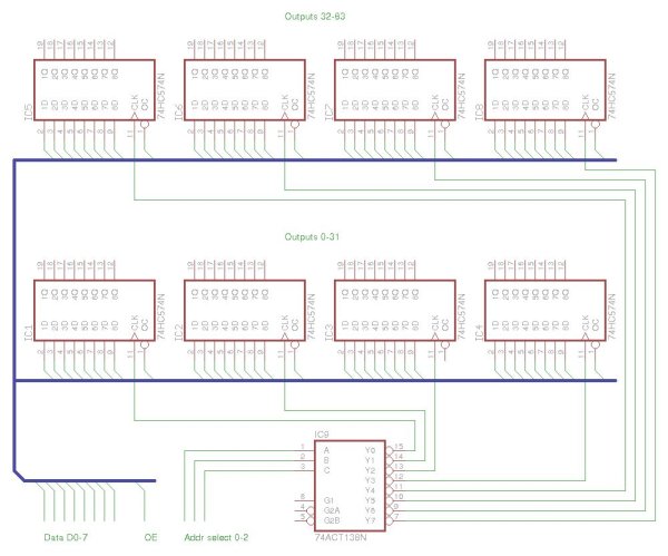
To get get the required 64 output lines needed for the LED anodes, we will create a simple multiplexer circuit. This circuit will multiplex 11 IO lines into 64 output lines.
The multiplexer is built by using a component called a latch or a flip-flop. We will call them latches from here on.
This multiplexer uses an 8 bit latch IC called 74HC574. This chip has the following pins:
- 8 inputs (D0-7)
- 8 outputs (Q0-7)
- 1 “latch” pin (CP)
- 1 output enable pin (OE)
The job of the latch is to serve as a kind of simple memory. The latch can hold 8 bits of information, and these 8 bits are represented on the output pins. Consider a latch with an LED connected to output Q0. To turn this LED on, apply V+ (1) to input D0, then pull the CP pin low (GND), then high (V+).
When the CP pin changes from low to high, the state of the input D0 is “latched” onto the output Q0, and this output stays in that state regardless of future changes in the status of input D0, until new data is loaded by pulling the CP pin low and high again.
To make a latch array that can remember the on/off state of 64 LEDs we need 8 of these latches. The inputs D0-7 of all the latches are connected together in an 8 bit bus.
To load the on/off states of all the 64 LEDs we simply do this: Load the data of the first latch onto the bus. pull the CP pin of the first latch low then high. Load the data of the second latch onto the bus. pull the CP pin of the second latch low then high. Load the data of the third latch onto the bus. pull the CP pin of the third latch low then high. Rinse and repeat.
The only problem with this setup is that we need 8 IO lines to control the CP line for each latch. The solution is to use a 74HC138. This IC has 3 input lines and 8 outputs. The input lines are used to control which of the 8 output lines that will be pulled low at any time. The rest will be high. Each out the outputs on the 74HC138 is connected to the CP pin on one of the latches.
The following pseudo-code will load the contents of a buffer array onto the latch array:
// PORT A = data bus
// PORT B = address bus (74HC138)
// char buffer[8] holds 64 bits of data for the latch array
PORTB = 0x00; // This pulls CP on latch 1 low.
for (i=0; i < 8; i++)
{
PORTA = buffer[i];
PORTB = i+1;
}
The outputs of the 74HC138 are active LOW. That means that the output that is active is pulled LOW. The latch pin (CP) on the latch is a rising edge trigger, meaning that the data is latched when it changes from LOW to HIGH. To trigger the right latch, the 74HC138 needs to stay one step ahead of the counter i. If it had been an active HIGH chip, we could write PORTB = i; You are probably thinking, what happens when the counter reaches 7, that would mean that the output on PORTB is 8 (1000 binary)on the last iteration of the for() loop. Only the first 8 bits of PORT B are connected to the 74HC138. So when port B outputs 8 or 1000 in binary, the 74HC138 reads 000 in binary, thus completing its cycle. (it started at 0). The 74HC138 now outputs the following sequence: 1 2 3 4 5 6 7 0, thus giving a change from LOW to HIGH for the current latch according to counter i.
Step 9: IO port expansion, alternative solution
There is another solution for providing more output lines. We went with the latch based multiplexer because we had 8 latches available when building the LED cube.
You can also use a serial-in-parallel out shift register to get 64 output lines. 74HC164 is an 8 bit shift register. This chip has two inputs (may also have an output enable pin, but we will ignore this in this example).
- data
- clock
Every time the clock input changes from low to high, the data in Q6 is moved into Q7, Q5 into Q6, Q4 into Q5 and so on. Everything is shifted one position to the right (assuming that Q0 is to the left). The state of the data input line is shifted into Q0.
The way you would normally load data into a chip like this, is to take a byte and bit-shift it into the chip one bit at a time. This uses a lot of CPU cycles. However, we have to use 8 of these chips to get our desired 64 output lines. We simply connect the data input of each shift register to each of the 8 bits on a port on the micro controller. All the clock inputs are connected together and connected to a pin on another IO port.
This setup will use 9 IO lines on the micro controller.
In the previous solution, each byte in our buffer array was placed in it’s own latch IC. In this setup each byte will be distributed over all 8 shift registers, with one bit in each.
The following pseudo-code will transfer the contents of a 64 bit buffer array to the shift registers.
// PORT A: bit 0 connected to shift register 0’s data input, bit 1 to shift register 1 and so on.
// PORT B: bit 0 connected to all the clock inputs
// char buffer[8] holds 64 bits of data
for (i=0; i < 8; i++)
{
PORTB = 0x00; // Pull the clock line low, so we can pull it high later to trigger the shift register
PORTA = buffer[i]; // Load a byte of data onto port A
PORTB = 0x01; // Pull the clock line high to shift data into the shift registers.
}
This is perhaps a better solution, but we had to use what we had available when building the cube. For the purposes of this instructable, we will be using a latch based multiplexer for IO port expansion. Feel free to use this solution instead if you understand how they both work.
With this setup, the contents of the buffer will be “rotated” 90 degrees compared to the latch based multiplexer. Wire up your cube accordingly, or simply just turn it 90 degrees to compensate 😉
Step 10: Power supply considerations
This step is easy to overlook, as LEDs themselves don’t draw that much current. But remember that this circuit will draw 64 times the mA of your LEDs if they are all on. In addition to that, the AVR and the latch ICs also draws current. To calculate the current draw of your LEDs, connect a led to a 5V power supply with the resistor you intend to use, and measure the current in mA. Multiply this number by 64, and you have the power requirements for the cube itself. Add to that 15-20 mA for the AVR and a couple of mA for each latch IC.Our first attempt at a power supply was to use a step-down voltage regulator, LM7805, with a 12V wall wart. At over 500mA and 12V input, this chip became extremely hot, and wasn’t able to supply the desired current.
We later removed this chip, and soldered a wire from the input to the output pin where the chip used to be.
We now use a regulated computer power supply to get a stable high current 5V supply.
Step 11: Buy a power supply
If you don’t have the parts necessary to build a 5V PSU, you can buy one. eBay is a great place to buy these things. Search for “5v power supply” and limit the search to “Business & Industrial”, and you’ll get a lot of suitable power supplies. About 15 bucks will get you a nice PSU.
Step 12: Build a power supply
A couple of years before we built the LED cube, we made our self a nice little lab power supply from an old external SCSI drive. This is what we have been using to power the LED cube. PC power supplies are nice, because they have regulated 12V and 5V rails with high Ampere ratings. You can use either a regular AT or ATX power supply or and old external hard drive enclosure.
If you want to use an ATX power supply, you have to connect the green wire on the motherboard connector to ground (black). This will power it up.
External hard drive enclosures are especially nice to use as power supplies. They already have a convenient enclosure. The only thing you have to do is to add external power terminals.
Power supplies have a lot of wires, but the easiest place to get the power you need is through a molex connector. That is the kind of plug you find on hard drives (before the age of S-ATA).
Black is GND Yellow is +12V Red is +5V
Here is an image of our lab PSU. We have 12V output, 5V output with an ampere meter and 5V output without an ampere meter. We use the second 5V output to power an 80mm PC fan to suck or blow fumes away when we solder.
We won’t get into any more details of how to make a power supply here. I’m sure you can find another instructable on how to do that.
Step 13: Choose your LEDs
You want the LED cube to be equally visible from all sides. Therefore we strongly recommend using diffused LEDs. A clear LED will shoot the majority of it’s light out the top of the LED. A diffused LED will be more or less equally bright from all sides. Clear LEDs also create another problem. If your cube is made up of clear LEDs. The LEDs will also partially illuminate the LEDs above them, since most of the light is directed upwards. This creates some unwanted ghosting effects. We actually ordered diffused LEDs from eBay, but got 1000 clear LEDs instead. Shipping them back to China to receive a replacement would have taken too much time, so we decided to used the clear LEDs instead. It works fine, but the cube is a lot brighter when viewed from the top as opposed to the sides.The LEDs we ordered from eBay were actually described as “Defused LEDs”. Maybe we should have taken the hint 😉 Defusing is something you do to a bomb when you want to prevent it from blowing up, hehe.
2)
Larger LEDs gives you a bigger and brighter pixel, but since since the cube is 8 layers deep, you want enough room to see all the way through to the furthest level. We went with 3mm LEDs because we wanted the cube to be as “transparent” as possible. Our recommendation is to use 3mm diffused LEDs.
3)
You can buy very cheap lots of 1000 LEDs on eBay. But keep in mind that the quality of the product may be reflected in it’s price. We think that there is less chance of LED malfunction if you buy better quality/more expensive LEDs.
4)
Square LEDs would probably look cool to, but then you need to make a soldering template that can accommodate square LEDs. With 3mm round LEDs, all you need is a 3mm drill bit.
5)
Since the cube relies on multiplexing and persistence of vision to create images, each layer is only turned on for 1/8 of the time. This is called a 1/8 duty cycle. To compensate for this, the LEDs have to be bright enough to produce the wanted brightness level at 1/8 duty cycle.
6)
Leg length. The cube design in this instructable uses the legs of the LEDs themselves as the skeleton for the cube. The leg length of the LEDs must be equal to or greater than the distance you want between each LED.
Step 14: Choose your resistors
If your LEDs came with a data sheet, there should be some ampere ratings in there. Usually, there are two ratings, one mA for continuous load, and mA for burst loads. The LEDs will be running at 1/8 duty cycle, so you can refer to the burst rating.2)
The 74HC574 also has some maximum ratings. If all the LEDs on one anode column are on, this chip will supply current 8/8 of the time. You have to keep within the specified maximum mA rating for the output pins. If you look in the data sheet, You will find this line: DC Output Source or Sink Current per Output Pin, IO: 25 mA. Also there is a VCC or GND current maximum rating of 50mA. In order not to exceed this, your LEDs can only run at 50/8 mA since the 74HC574 has 8 outputs. This gives you 6.25 mA to work with.3)
The transistors have to switch on and off 64 x the mA of your LEDs. If your LEDs draw 20mA each, that would mean that you have to switch on and off 1.28 Ampere.
The only transistors we had available had a maximum rating of 400mA.
We ended up using resistors of 100 ohms.
While you are waiting for your LED cube parts to arrive in the mail, you can build the guy in the picture below: http://www.instructables.com/id/Resistor-man/
Step 15: Choose the size of your cube
We wanted to make the LED cube using as few components as possible. We had seen some people using metal rods for their designs, but we didn’t have any metal rods. Many of the metal rod designs also looked a little crooked. We figured that the easiest way to build a led cube would be to bend the legs of the LEDs so that the legs become the scaffolding that holds the LEDs in place. We bent the cathode leg on one of the LEDs and measured it to be 26 mm from the center of the LED. By choosing a LED spacing of 25mm, there would be a 1mm overlap for soldering. (1 inch = 25.4mm)
With a small 3mm LED 25mm between each led gave us plenty of open space inside the cube. Seeing all the way through to the furthest layer wouldn’t be a problem. We could have made the cube smaller, but then we would have to cut every single leg, and visibility into the cube would be compromised.
Our recommendation is to use the maximum spacing that your LED can allow. Add 1mm margin for soldering.
Step 16: How to make straight wire
In order to make a nice looking LED Cube, you need some straight steel wire. The only wire we had was on spools, so it had to be straightened. Our first attempt at this failed horribly. We tried to bend it into a straight wire, but no matter how much we bent, it just wasn’t straight enough. Then we remembered an episode of “How it’s made” from the Discovery Channel. The episode was about how they make steel wire. They start out with a spool of really thick wire, then they pull it through smaller and smaller holes. We remembered that the wire was totally straight and symmetrical after being pulled like that.
So we figured we should give pulling a try, and it worked! 100% straight metal wire from a spool!
Here is how you do it.
- cut of the length of wire you need from the spool, plus an inch or two.
- Remove the insulation, if any.
- Get a firm grip of each end of the wire with two pairs of pliers
- Pull hard!
- You will feel the wire stretch a little bit.
You only need to stretch it a couple of millimeters to make it nice and straight.
If you have a vice, you can secure one end in the vice and use one pair of pliers. This would probably be a lot easier, but we don’t own a vice.
Step 17: Practice in small scale
Whenever Myth Busters are testing a complex myth, they start by some small scale experiments. We recommend that you do the same thing. Before we built the 8x8x8 LED cube, we started by making a smaller version of it, 4x4x4. By making the 4x4x4 version first, you can perfect your cube soldering technique before starting on the big one.
Check out our 4x4x4 LED cube instructable for instructions on building a smaller “prototype”.
Step 18: Build the cube: create a jig
Find a piece of wood or plastic that is larger than the size of your cube.2)
Find a drill bit that makes a hole that fits a LED snugly in place. You don’t want it to be to tight, as that would make it difficult to remove the soldered layer from the jig without bending it. If the holes are too big, some of the LEDs might come out crooked.3)
Use a ruler and an angle iron to draw up a grid of 8 by 8 lines intersecting at 64 points, using the LED spacing determined in a previous step.
4)
Use a sharp pointy object to make indentions at each intersection. These indentions will prevent the drill from sliding sideways when you start drilling.
5)
Drill out all the holes.
6)
Take an LED and try every hole for size. If the hole is too snug, carefully drill it again until the LED fits snugly and can be pulled out without much resistance.
7)
Somewhere near the middle of one of the sides, draw a small mark or arrow. A steel wire will be soldered in here in every layer to give the cube some extra stiffening.
Step 19: Build the cube: soldering advice
First of all, you need to keep your soldering iron nice and clean. That means wiping it on the sponge every time you use it. The tip of your soldering iron should be clean and shiny. Whenever the you see the tip becoming dirty with flux or oxidizing, that means loosing it’s shinyness, you should clean it. Even if you are in the middle of soldering. Having a clean soldering tip makes it A LOT easier to transfer heat to the soldering target.
When soldering so close to the LED body, you need to get in and out quickly. Wipe your iron clean. Apply a tiny amount of solder to the tip. Touch the part you want to solder with the side of your iron where you just put a little solder. Let the target heat up for 0.5-1 seconds, then touch the other side of the target you are soldering with the solder. You only need to apply a little bit. Only the solder that is touching the metal of both wires will make a difference. A big blob of solder will not make the solder joint any stronger. Remove the soldering iron immediately after applying the solder.Mistakes and cool down
If you make a mistake, for example if the wires move before the solder hardens or you don’t apply enough solder. Do not try again right away. At this point the LED is already very hot, and applying more heat with the soldering iron will only make it hotter. Continue with the next LED and let it cool down for a minute, or blow on it to remove some heat.
Solder
We recommend using a thin solder for soldering the LEDs. This gives you a lot more control, and enable you to make nice looking solder joints without large blobs of solder. We used a 0.5 mm gauge solder. Don’t use solder without flux. If your solder is very old and the flux isn’t cleaning the target properly, get newer solder. We haven’t experienced this, but we have heard that it can happen.
Are we paranoid?
When building the 8x8x8 LED Cube, we tested each and every LED before using it in the cube. We also tested every LED after we finished soldering a layer. Some of the LEDs didn’t work after being soldered in place. We considered these things before making a single solder joint. Even with careful soldering, some LEDs were damaged.
The last thing you want is a broken LED near the center of the cube when it is finished. The first and second layer from the outside can be fixed afterwards, but any further in than that, and you’ll need endoscopic surgical tools 😉
Step 20: Build the cube: test the LEDs
We got our LEDs from eBay, really cheap! We tested some of the LED before we started soldering, and randomly stumbled on a LED that was a lot dimmer than the rest. So we decided to test every LED before using it. We found a couple of dead LEDs and some that were dimmer than the rest. It would be very bad to have a dim LED inside your finished LED cube, so spend the time to test the LEDs before soldering! This might be less of a problem if you are using LEDs that are more expensive, but we found it worth while to test our LEDs.
Get out your breadboard, connect a power supply and a resistor, then pop the LEDs in one at a time. You might also want to have another LED with its own resistor permanently on the breadboard while testing. This makes it easier to spot differences in brightness.
Step 21: Build the cube: solder a layer
Bend the cathode leg of each LED 90 degrees. Make sure the legs are bent in the same direction on all the LEDs. Looking at the LED sitting in a hole in the template with the notch to the right, we bent the leg upwards.
Start by placing the top right LED in the template. Then place the one to the left, positioning it so that it’s cathode leg is touching the cathode leg of the previous LED. Rinse and repeat until you reach the left LED. Solder all the joints.3) Solder all 8 columns
If you are right handed, we recommend you start with the column to the left. That way your hand can rest on the wooden template when you solder. You will need a steady hand when soldering freehand like this. Start by placing the LED second from the top, aligning it so it’s leg touches the solder joint from the previous step. Then place the LED below that so that the cathode leg touches the LED above. Repeat until you reach the bottom. Solder all the joints.
4) Add braces
You now have a layer that looks like a comb. At this point the whole thing is very flimsy, and you will need to add some support. We used one bracing near the bottom and one near the middle. Take a straight peace of wire, roughly align it where you want it and solder one end to the layer. Fine tune the alignment and solder the other end in place. Now, make solder joints to the remaining 6 columns. Do this for both braces.
5) Test all the LEDs
This is covered in the next step. Just mentioning here so you don’t remove the layer just yet.
6) Remove the layer
The first layer of your LED cube is all done, now all you have to do is remove it from the template. Depending on the size of your holes, some LEDs might have more resistance when you try to pull it out. Simply grabbing both ends of the layer and pulling would probably break the whole thing if a couple of the LEDs are stuck.
Start by lifting every single LED a couple of millimeters. Just enough to feel that there isn’t any resistance. When all the LEDs are freed from their holes, try lifting it carefully. If it is still stuck, stop and pull the stuck LEDs out.
Repeat 8 times!
Note on images:
If you are having trouble seeing the detail in any of our pictures, you can views the full resolution by clicking on the little i icon in the top left corner of every image. All our close up pictures are taken with a mini tripod and should have excellent macro focus. On the image page, choose the original size from the “Available sizes” menu on the left hand side.
Step 22: Build the cube: test the layer
Soldering that close to the body of the LED can damage the electronics inside. We strongly recommend that you test all LEDs before proceeding. Connect ground to the tab you left sticking out at the upper right corner. Connect a wire to 5V through a resistor. Use any resistor that lights the LED up and doesn’t exceed its max mA rating at 5V. 470 Ohm would probably work just fine. Take the wire and tap it against all 64 anode legs that are sticking up from your template. If a LED doesn’t flash when you tap it, that means that something is wrong.
1) Your soldering isn’t conducting current.
2) The LED was overheated and is broken.
3) You didn’t make a proper connection between the test wire and the led. (try again).
If everything checks out, pull the layer from the cube and start soldering the next one.
Step 23: Build the cube: straigthen the pins
In our opinion, a LED cube is a piece of art and should be perfectly symmetrical and straight. If you look at the LEDs in your template from the side, they are probably bent in some direction. You want all the legs to point straight up, at a 90 degree angle from the template. While looking at the template from the side, straighten all the legs. Then rotate the template 90 degrees, to view it from the other side, then do the same process.
You now have a perfect layer that is ready to be removed from the template.
Step 24: Build the cube: bend the pins
Step 25: Build the cube: solder the layers together
Now comes the tricky part, soldering it all together! The first two layers can be quite flimsy before they are soldered together. You may want to put the first layer back in the template to give it some stability. In order to avoid total disaster, you will need something to hold the layer in place before it is soldered in place. Luckily, the width of a 9V battery is pretty close to 25 mm. Probably closer to 25.5-26mm, but that’s OK.
Warning: The 9 volts from a 9V battery can easily overload the LEDs if the contacts on the battery comes in contact with the legs of the LEDs. We taped over the battery poles to avoid accidentally ruining the LEDs we were soldering.
We had plenty of 9V batteries lying around, so we used them as temporary supports.
Start by placing a 9V battery in each corner. Make sure everything is aligned perfectly, then solder the corner LEDs.
Now solder all the LEDs around the edge of the cube, moving the 9V batteries along as you go around. This will ensure that the layers are soldered perfectly parallel to each other.
Now move a 9V battery to the middle of the cube. Just slide it in from one of the sides. Solder a couple of the LEDs in the middle.
The whole thing should be pretty stable at this point, and you can continue soldering the rest of the LEDs without using the 9V batteries for support.
However, if it looks like some of the LEDs are sagging a little bit, slide in a 9V battery to lift them up!
When you have soldered all the columns, it is time to test the LEDs again. Remember that tab sticking out from the upper right corner of the layer, that we told you not to remove yet? Now it’s time to use it. Take a piece of wire and solder the tab of the bottom layer to the tab of the layer you just soldered in place.
Connect ground to the the ground tab.
Test each led using the same setup as you used when testing the individual layers. Since the ground layers have been connected by the test tabs, and all the anodes in each columns are connected together, all LEDs in a column should light up when you apply voltage to the top one. If the LEDs below it does not light up, it probably means that you forgot a solder joint! It is A LOT better to figure this out at this point, rather than when all the layers are soldered together. The center of the cube is virtually impossible to get to with a soldering iron.
You now have 2/8 of your LED cube soldered together! Yay!
For the next 6 layers, use the exact same process, but spend even more time aligning the corner LEDs before soldering them. Look at the cube from above, and make sure that all the corner LEDs are on a straight line when looking at them from above.
Rinse and repeat!
Step 26: Build the cube: create the base
We didn’t have any fancy tools at our disposal to create a fancy stand or box for our LED cube. Instead, we modified the template to work as a base for the cube. We encourage you to make something cooler than we did for your LED cube!For the template, we only drilled a couple of mm into the wood. To transform the template into a base, we just drilled all the holes through the board. Then we drilled 8 smaller holes for the 8 cathode wires running up to the 8 cathode layers.
Of course, you don’t want to have your LED cube on a wood colored base. We didn’t have any black paint lying around, but we did find a giant black magic marker! Staining the wood black with a magic marker worked surprisingly well! I think the one we used had a 10mm point.
Step 27: Build the cube: mount the cube
Mount the cube. That sounds very easy, but it’s not. You have to align 64 LED legs to slide through 64 holes at the same time. It’s like threading a needle, times 64.We found it easiest to start with one end, then gradually popping the legs into place. Use a pen or something to poke at the LED legs that miss their holes. Once all 64 LED legs are poking through the base, carefully turn it on it’s side. Then bend all 64 legs 90 degrees. This is enough to hold the cube firmly mounted to the base. No need for glue or anything else.
Step 28: Build the cube: cathode risers
You now have a LED cube with 64 anode connections on the underside of the base. But you need to connect the ground layers too. Remember those 8 small holes you drilled in a previous step? We are going to use them now. Make some straight wire using the method explained in a previous step.
We start with ground for layer 0. Take a short piece of straight wire, Make a bend approximately 10mm from the end. Poke it through the hole for ground layer 0. Leave 10mm poking through the underside of the base. Position it so that the bend you made rests on the back wire of ground layer 0. Now solder it in place.
Layer 1 through 7 are a little trickier. We used a helping hand to hold the wire in place while soldering.
Take a straight piece of wire and bend it 90 degrees 10mm from the end. Then cut it to length so that 10mm of wire will poke out through the underside of the base.
Poke the wire through the hole and let the wire rest on the back wire of the layer you are connecting. Clamp the helping hand onto the wire, then solder it in place.
Rinse and repeat 7 more times.
Carefully turn the cube on it’s side and bend the 8 ground wires 90 degrees.
Step 29: Build the cube: attach cables
64+8 wires have to go from the controller to the LED cube. We used ribbon cable to make things a little easier.The ground layers use an 8-wire ribbon cable. The cathodes are connected with 4 16-wire ribbon cables. Each of these ribbon cables are split in two at either end, to get two 8-wire cables.
At the controller side, we attached 0.1″ female header connectors. These plug into standard 0.1″ single row PCB header pins.
The header connector is a modular connector that comes in two parts, metal inserts and a plastic body.
The metal inserts are supposed to be crimped on with a tool. We didn’t have the appropriate tool on hand, so we used pliers. We also added a little solder to make sure the wires didn’t fall of with use.
2) Crimp or solder on the metal inserts.
3) Insert the metal insert into the plastic connector housing.
4) Solder the 8-wire ribbon cable to the cathode risers. Pre-tin the cables before soldering!
5) Solder in the rest of the cables. The red stripe on the first wire indicates that this is bit 0.
6) Tighten the screws on the strain relief to make sure everything stays in place.
7) Connect all the ribbon cables to the PCBs in the correct order. See pictures below. Our 8 wire ribbon cable didn’t have a red wire. Just flip the connector 180 degrees if your cube is upside-down.
Step 30: Build the controller: layout
We took out the biggest type of PCB we had available (9x15cm) and started experimenting with different board layouts. It soon became clear that cramming all the components onto one board wasn’t a good solution. Instead we decided to separate the latch array and power supply part of the circuit and place it on a separate board. A ribbon cable transfers data lines between the two boards.
Choosing two separate boards was a good decision. The latch array took up almost all the space of the circuit board. There wouldn’t have been much space for the micro controller and other parts.
You may not have the exact same circuit boards as we do, or may want to arrange your components in a different way. Try to place all the components on your circuit board to see which layout best fits your circuit board.
Step 31: Build the controller: clock frequency
We use an external crystal of 14.7456 MHz to drive the ATmega system clock. You may be thinking that this is an odd number to use, and why we didn’t run the ATmega at the 16MHz it is rated for. We want to be able to control the LED cube from a computer, using RS232. Serial communication requires precise timing. If the timing is off, only by a little bit, some bits are going to be missed or counted double from time to time. We won’t be running any error correcting algorithms on the serial communications, so any error over the line would be represented in the LED cube as a voxel being on or off in the wrong place.
To get flawless serial communication, you have to use a clock frequency that can be divided by the serial frequency you want to use.
14.7456 MHz is dividable by all the popular RS232 baud rates.
- (14.7456MHz*1000*1000) / 9600 baud = 1536.0
- (14.7456MHz*1000*1000) / 19200 baud = 768.0
- (14.7456MHz*1000*1000) / 38400 baud = 384.0
- (14.7456MHz*1000*1000) / 115200 baud = 128.0
The formula inside the parentheses converts from MHz to Hz. First *1000 gives you KHz, the next Hz.
As you can see all of these RS232 baud rates can be cleanly divided by our clock rate. Serial communication will be error free!
Step 32: Build the controller: protoboard soldering advice
We see people do a lot of weird stuff when they solder on prototype PCBs. Before you continue, we just want to share with you the process we use to create tracks on prototype PCBs with solder eyes. Once you master this technique, you will probably start using it a lot.
1) Fill each point of the track you want to make with solder.
2) Connect every other points by heating them and adding a little solder.
3) Connect the 2-hole long pieces you now have spanning the desired track.
4) Look how beautiful the result is.
You can see in the video how we do it. We had to touch some of the points twice to join them. It was a bit hard to have the camera in the way when we were soldering 😉
For more detail: LED Cube 8x8x8