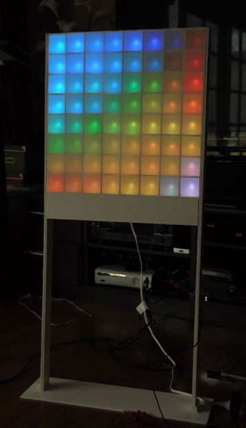
Lampduino is a computer-controlled free-standing floor lamp, comprised of an 8×8 RGB LED matrix. The lamp stands 45″ high and 18″ wide. Light emanates from both sides. It has various display modes, as well as an included editor for creating animations. The lamp is controlled via an application running on a PC host. The display modes include realtime drawing, playback of previously created animations, snow, meteor, plasma, and synchronization with music. With its endless available colors, Lampduino can also be used for color therapy, or as a mood light. When running standalone, without a computer, it plays a soothing plasma simulation..
NOTE: Any flickering in the videos below is caused by video camera aliasing. Persistence of vision makes it look flicker-free by the naked eye.
Step 1: Bill of Materials
Parts List
(64) 5mm common anode RGB LED’s. I bought mine on eBay
(1) ITead Studio Colorduino or an Arduino with Itead Studio Colors Shield
(1) large piece of foamcore board. This kind of board can be found in most office or artist supply shops. It is a foam core sandwiched between two sheets of thick paper. I recycled a 45×30″ piece that had a previous life as an advertising poster.
(2) 18×18″ pieces of matte drafting film. I cut them out of a single 24×36″ sheet of .003″ thick Grafix 2-sided matte drafting film.
lots of 30AWG kynar-insulated wrapping wire. I bought 3 50 feet rolls at Radio Shack, one each of red/white/blue. 150 feet is overkill, but it’s a lot easier to work with different colors of wire.
(2) 16-pin male headers
(1) 5V 1A power supply. I repurposed a wall wart from a broken gadget.
For music synchronization, a few additional parts are needed. See the Music Synchronization step.
Tools
x-acto knife
hot glue gun
wire stripping/wrapping tool
straight edge
ruler
Step 2: Lay Out the Grid Pieces
Each of the 64 LED’s in the matrix is enclosed in a 2x2x2″ cell. First, draw out your cutting lines in pencil on your foam board. You will need 14 grid pieces to form the core of the matrix. I found that it’s convenient to lay out the cuts in pairs that are facing each other. This way, you can cut two slots at once.
Cutting foam board requires a very sharp knife. I used a #11 X-acto blade. If your knife is dull, instead of cleanly cutting through the foam, it will just catch on it, ripping out little chunks of foam. It’s not very pretty. I went through 3 blades while making the matrix. Change the blade when the cuts start to get degraded. I found it hard to make a single clean cut through the 3 layers of the foam board; this method often left me with little chunks of ripped out foam. It’s easier to make clean cuts if you first make a deep score with the knife against the straight edge. Make sure the score goes through the whole top layer of paper, and into the foam. Then you can remove the straight edge, and just run the knife repeatedly into the score until you get through the layers.
First, cut the slots. You can pop them out at this stage, or wait until the next step.
Step 3: Cut out the Grid Pieces
Step 4: Cut Slits in the Grid Pieces
Cut horizontal slits into the grid pieces, one in the center of each cell. Make sure the slits go through all the layers. You needn’t be super precise, but they should be about 1/2″ long. The LED’s will be held in place in a later step by pressing the wires into the slits.
Step 5: Assemble the Grid Pieces
Assemble the 14 grid pieces to form the core of your matrix. Don’t glue it yet. You might have to take it apart several times while wiring it up. I painted over the printed bits with white spray paint before proceeding.
Step 6: Wire up the 8 LED Strands
I chose wire wrap as the wiring method for this project because:
- it’s cheap
- there are no toxic fumes
- there is no risk of overheating and destroying LED’s
- it’s easy to undo, so repairs are easier
- it’s relatively quick to do
- it’s as reliable as soldering – perhaps more reliable, since there’s no risk of cold-soldered joints
- the wire is so thin that it can be threaded into the gaps between the foam matrix pieces
If you are not familiar with wire wrapping, Wikipedia has a detailed introduction to the technique. I was a bit worried that the 30AWG wire would be too thin to handle the current running through the matrix. I consulted some tables on the Internet, I found that 30AWG solid wire has a resistance of 105.2 Ω/1000 ft. I estimated an upper bound of 4 ft of wire, so that’s ~.4Ω – probably insignificant for this application. Next, I found that the current carrying ability (Ampacity) is estimated at .144A by most tables, but one actually had it listed at .86A. The LED’s I used run at a maximum of 20mA per color. In a column, a maximum of 1 LED at a time is lit, so it’s definitely in spec. On the other hand, if a whole row is driven w/ the with all 3 colors lit, we can end up with 8 x 3 x 20mA = 480mA. This is way over the .144A spec, but below the .86A spec. I decided to just try it, and if I encountered problems, I would put multiple wires in parallel for the rows. After testing, I found that using single wires for the rows worked fine … they did not heat up at all.
The schematic diagram for a common anode 8×8 RGB matrix is depicted above. We are going to wire our matrix, composed of 5mm LED’s, in the same fashion.
We need a total of 8 strands of 8 LED’s. Each pair of LED’s is connected with three 4″ pieces of wire. The anode is the lead which is slightly longer. In my photo above, the pins, from left to right, are Blue/Green/Anode/Red.
The red wires connect the red channel, the white wires the green channel, and the blue wires the blue channel. 4″ may sound a bit long, since the cells are only 2″ wide, but I when you account for stripping the wire on both ends, and leaving enough slack to manipulate the LED’s in while assembling the grid, 4″ is a good length. You will need 49 4″ pieces of wire for each color – 147 pieces total. While working on this step, I discovered a few things which make for a quicker and cleaner job:
- orient the pins of your LED’s the same way while wiring them (e.g. blue pin on the left, red pin on the right)
- connect the R/G/B wires between each pair of LED’s before moving to the next LED. At first, I was connecting all the reds, then all the blues, then all the greens. This method was a bit messier.
- spread the pins apart a bit before wrapping. Otherwise, the wrapping tool will get caught on the adjacent wraps as you try to insert it
- start the first wrap about halfway into each lead
- when connecting the second wire on each lead, just stack the wrap against the previous wrap.
Note that the anode pin is left unconnected at this stage. This is because the anodes form the rows, which are perpendicular to the R/G/B cathode wires, which form the columns.
Step 7: 8 LED Strands
Step 8: Thread the LED Strands into the Matrix
Step 9: Wire up the Rows
Next, flip the matrix over so that the slots running perpendicular to the strands are on top. Wiring up the rows is a bit trickier, because we’re working in close quarters. However, unlike the columns, the rows need only 1 wire per LED, a total of 49 wires. Here’s where the slack we created by using 4″ long wires comes in handy. It lets us manipulate the LED’s more easily. Connect the anodes with 6″ lengths of wire. The yellow wires in my photo are the anode connections. I had an old spool of yellow wire, but it ran out before I was done with the rows. It’s easier to wire up all the anodes before you insert the LED’s into the slits, as pictured.
Step 10: Route the Wires
I ran all of my column wires through a single slot in the matrix ,to the bottom. I cut slots in the bottom for running the row wires. This was a mistake, because now my columns are horizontal, and the rows are vertical. The correct orientation is the reverse: the column wires should out the bottom, and the row wires down the side.
Step 11: Connect the Matrix to the Colorduino
Wrap the 32 wires coming out of the matrix into the two 18-pin male headers. Note that you have to wrap on the short end of each pin, because we need to long end to plug into the Colorduino. The headers on the Colorduino are clearly labeled. The red and blue pins go on one header, while the anodes and the green go on the other. Note that the anodes are labeled VCC on the Colorduino, and that there are 4 anode pins on each side of the 8 green pins. The origin of our matrix, (0,0), is located at the bottom left. Therefore, pin 1 of red/green/blue should connect to the leftmost column. Similarly, pin 1 of the VCC (anode) pins should connect to the bottom row.
Before plugging the matrix into the Colorduino, it is a good idea to test it, and check for shorts, as well as correctness of the header wiring. I used a 5V power source, hooked up to a 100Ω resistor, to test each individual LED. I was pleasantly surprised to find that I didn’t have a single short circuit in the matrix.
Step 12: Finish Constructing the Matrix
After the wiring and testing is done, you can attach the top, bottom, and sides. Note that there is an 3″ long extension of the side pieces on the bottom. This is to accomodate the Colorduino.
Step 13: Add the Legs and Stand
My intention is to wrap the matrix in wood, and attach it to a wooden stand. However, due to time constraints, I decided to first prototype it using foam board. I cut two 45×2″ pieces to form the legs. For greater stability, the lower section is two layers thick. The base is 22×6″. The box directly beneath the matrix, which houses the Colorduino, uses two 18×3″ sheets for its sides.
Step 14: Cut and Attach the Drafting Film
Cut two 18×18″ squares of drafting film. Attach one to each side of the matrix. I made a mistake, and used hot glue. Hot glue is hard to deal with when gluing large objects, because it cools down too fast. I forgot that when I built my 5×5 matrix, I used Elmer’s glue instead. Elmer’s works a lot better, because it gives you time to pull the film tight, and get all the wrinkles out. Also, unlike hot glue, it doesn’t mar the look of the matrix with little shadows of glue blobs.
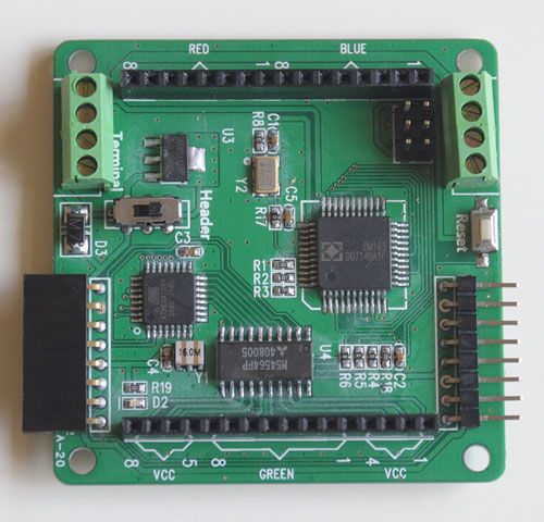
Step 15: Colorduino Description
An Arduino doesn’t have enough I/O pins, nor enough current output to drive an 8×8 RGB LED matrix. Therefore, one needs to interface it with external LED driver circuitry. The Colorduino is an Arduino variant, which is specialized for driving up to 192 LED’s (64 RGB LED’s). For a detailed description of the Colorduino, see my article, Itead Studio Colorduino – A Preview. Note that my Colorduino is a beta board. The production version, V1.3, has been released to manufacturing. It contains some minor tweaks, such a repositioning the ICSP header to a location that actually has enough space for you to plug in your programmer!
The Colorduino can be powered by 5V via the 8-pin header, or with 6.2-7.5V via the 4-pin green screw terminals. When switching between the two power sources, it is important to put the slider switch in the correct position. The Header position is for power through the VDD pin on the 8-pin header, and the Terminal position is for power via the VCC pins on the 4-pin green screw terminals.
The LED’s draw a lot of current. When I powered the Colorduino with either my Arduino or my USBtinyISP, I was not able to program it, because the LED’s draw too much current. Switching to a separate 5V 1A supply fixed the problem.
On drawback of using a dedicated board such as the Colorduino is that it doesn’t expose any I/O pins for external inputs. Therefore, many users connect them to another Arduino via I2C. Since I’m using it standalone, I connected my input to one of the I2C pins. There are actually a couple of other free I/O pins, such as INT0 and INT1, but they are not connected to any accessible headers, so you have to solder wires directly to the ATmega MCU to use them.
For more detail: Lampduino – an 8×8 RGB Floor Lamp