
Summary of Kaosduino: Create your own kaosillitaor using Arduino
This project is an open-source prototype of a Korg Kaossilator-style synthesizer built using an Arduino Uno. It utilizes a capacitive trackpad for touch-based sound generation, creating an 8-bit noisy aesthetic. The author modified the Adafruit PS2 library to handle faster data reading and implemented data prediction to mitigate signal errors caused by high CPU usage. While the design includes an LCD screen, it is noted as optional due to slow update rates.
Parts used in the Kaosduino:
- Trackpad from Adafruit
- Prototyping shield
- Pin headers
- PS2 breakout from Adafruit
- Arduino uno board
- LCD screen from Adafruit
- Homemade synth shield
- Wooden box
- Acrylic plate
- Two buttons
- Wire
- 2.2k Resistor
- 100n Capacitor
- 100u Capacitor
This project is a part of experiments done while doing an artist in residence at Instructables. You can see the other projects here.
Inspired by Korgs Kaossilator I took it upon myself to build an opensource version of it. This way people can design new ways of interacting with the touchpad. The basic principle is creating sound via a trackpad. This enables you to create an instrument with quite wobbly possibilities. The challenge is to program something that would enable you to create interesting sounds. This is also a challenge with the Kaossilator which get mixed reviews for the same reason. This is an initial prototype. It uses the an arduino as basic 8 bit sound engine and uses a capacitative trackpad from adafruit industries as the input device.
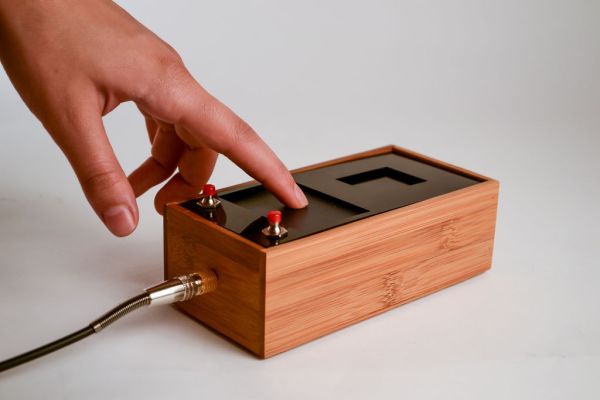
As seen in the video I have only programmed the first proof of concept so far. The arduino is able to generate 4 times as many concurrent voices and the envelope modulation has much more potential. I am looking forward to see if anybody adds new dimensions to it. I will update the code as I go along as well.
The design works with a few limitations. The synth used is a really simple 8 bit synth with the 8 bit noisy aesthetic qualities. Further the synth used requires quite a lot of CPU which has proven to be a challenge when reading the touch gestures from the trackpad. I had to rewrite the trackpad library from Adafruit to enable much faster readings. This enabled the synth and the trackpad to play sort-of-nice together, but sometimes it get wrong readings from the trackpad. This is solved by doing a little prediction of the data coming in and skipping it if the data seems implausible. I am sure this could be solved much more elegantly by using looking at the parity bit, but I have not gotten around to do this yet.
Step 1: Components and tools needed
The following componets are needed:
- Trackpad from Adafruit.
- Prototyping shield.
- Pin headers
- PS2 breakout from Adafruit (This is not necessary just simplifies the process).
- Arduino uno board.
- LCD screen from Adafruit. (Honestly I would leave this step out, since the update rate on the screen is rather slow and it is only a nice to have).
- Homemade synth shield based on the following synth instructable.
- Wooden box (I got mine from the container store in SF).
- Acrylic plate.
- Two buttons.
- Wire.
For the synth shield you will need:
- A prototyping shield.
- pin headers (the stackable ones).
- Wires
- 2.2k Resistor
- 100n Capacitor
- 100u Capacitor
The electronics can be done with basic soldering tools. The enclosure was made with a laser cutting some acrylics and a drillpress to make holes in the wooden box.
Step 2: Connect the lcd
As mentioned, you can build the box without the LCD. The LCD was an extra component to play with for me, but it turned out to be a really slow communication protocol resulting in the a slow frame rate This is amplified by the many resources the synth takes form the Arduino cpu. If you want to use it you will have to do the following:
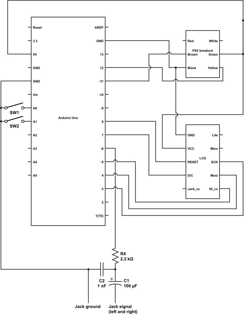
I used the following pins on the Arduino to connect the LCD (After connecting it I read a note about using hardware spi instead, that might be an option to get more speed out of it):
#define sclk 3
#define mosi 4
#define cs 5
#define dc 7
#define rst 8
Have a look at the diagram from step one to se the wiring.
I followed the tutorial from Adafruit.
Step 3: Connect the trackpad
For the trackpad to connect to the Arduino I used a ps2 breakout connector. This is not necessary, but it made the coloring consistent with the notes found in Adafruits example code.
Connect the brown wire to pin 11 on the Arduino and connect yellow wire to pin 12 on the Arduino. Connect the black wire to ground and connect Green wire to 5v on the Arduino (Yes the green wire is plus on the ps2 breakout). The two last wires red and white are not used in this case.
// PS2 uses two digital pins
#define PS2_DATA 11
#define PS2_CLK 12
- Trackpad from Adafruit.
- Prototyping shield.
- Pin headers
- PS2 breakout from Adafruit (This is not necessary just simplifies the process).
- Arduino uno board.
- LCD screen from Adafruit. (Honestly I would leave this step out, since the update rate on the screen is rather slow and it is only a nice to have).
- Homemade synth shield based on the following synth instructable.
- Wooden box (I got mine from the container store in SF).
- Acrylic plate.
- Two buttons.
- Wire.
For the synth shield you will need:
- A prototyping shield.
- pin headers (the stackable ones).
- Wires
- 2.2k Resistor
- 100n Capacitor
- 100u Capacitor
For more detail: Kaosduino: Create your own kaosillitaor using Arduino
- What inspired the creation of this project?
The project was inspired by the Korg Kaossilator to build an open-source version allowing users to design new ways of interacting with a touchpad. - How does the device generate sound?
Sound is created via a capacitive trackpad which serves as the input device for the Arduino-based 8-bit sound engine. - Why was the trackpad library rewritten?
The original library was too slow for the CPU requirements of the synth, so it was rewritten to enable much faster readings. - What issue occurs when reading touch gestures?
High CPU usage can lead to wrong readings from the trackpad, requiring data prediction to skip implausible data. - Is the LCD screen necessary for the project?
No, the LCD is not necessary because its communication protocol is slow and results in a low frame rate. - Can the Arduino generate multiple voices simultaneously?
Yes, the Arduino is able to generate four times as many concurrent voices in this proof of concept. - What materials were used for the enclosure?
The enclosure was made using a wooden box and laser-cut acrylic plates. - Which pins are used for the PS2 trackpad connection?
The brown wire connects to pin 11 and the yellow wire connects to pin 12 on the Arduino.
