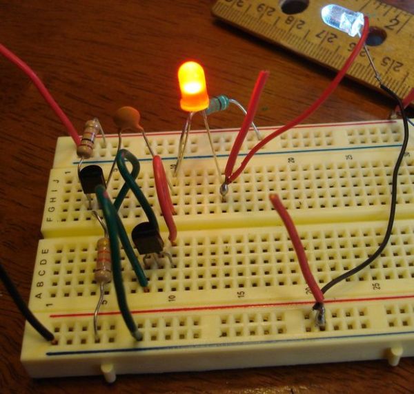
Yep, no transformer and no hard to get IC. But, … two transistors and other parts are required. I actually found this circuit by accident while roaming Colin Mitchell’s Talking Electronics website (talkingelectronics.com).
This website is very rich with examples and explanations of a huge variety of circuits. In fact, this website is so abundant in circuits that later on, I couldn’t find the circuit revealed here. Anyhow, I believe that the TE circuit can be considered “robust” as it works even if different parts are used.
red LED in series with the white LED, the circuit draws 15 milliamps @ 48 kHz.
But when using only the white LED, the circuit draws 17 ma @ 38 kHz.
The “Joule Thief” circuit using only easily found parts and no transformer might be attractive to many readers here. This is why I thought it was important to reveal this project.
But in my case, I am still tilted toward the simplicity of a “Joule Thief” circuit using little more than an IC and an Inductor, as revealed in my Instructable, “Joule Thief” Circuits – crude to modern…
And now, I recently had a reader has ask me where I could put a photoresistor in the two transistor “joule thief” circuit to make the circuit turn off in light and turn on in darkness. I really didn’t know but wired a photoresistor between the B plus and the base of the PNP transistor, Q1 (see first schematic below). This sort of worked but light didn’t always shut of the LED – not good enough. I then added another transistor to turn on and off the circuit, where this transistor is controlled by the CsS Radio Shack style photocell and a 10k ohm pot (old volume control). This seemed to work fine as the light/dark trip point could be easily adjusted by the pot (see second schematic below)…
For more detail: Joule Thief” – no IC and no Transformer

