Summary of JCB Machine
This article details the construction of a model JCB backhoe loader using an Arduino Nano, joystick modules, and servo motors. It outlines the necessary electronic components, 3D printed parts, and a step-by-step assembly process involving Fevikwik adhesive and precise shaft alignment to ensure functional movement of the arms and grippers.
Parts used in the Model JCB Machine:
- Arduino Nano
- Joystick Module (2 Nos)
- Servo Motor 180 degree (4 Nos)
- Male to Female Jumper Wire
- Male to Male Jumper Wire
- Dc Shaft Motor (2 Nos)
- Push Button (2 Nos)
- Mini Bread board
- Power Supply 5 V 1 Amps
- 3D Assembly Parts
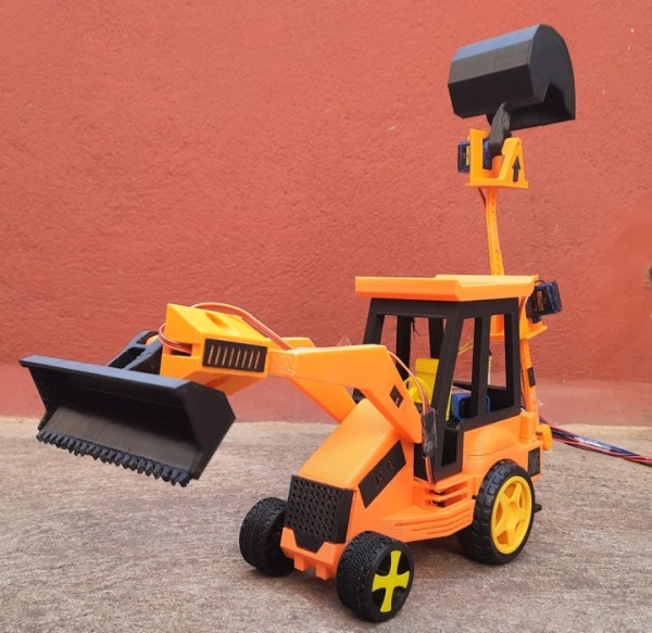
JCB Machine is very popular because it is heavy-duty construction equipment in the civil industry. JCB is also known as the backhoe loader. It can be used to load or unload the trucks very quickly.
It is used for the construction of roads, loading and unloading of trucks, and many more things.
Every construction company uses it because it is fast enough and it can lift heavy weight.
Step 1: Video
Step 2: Materials Used
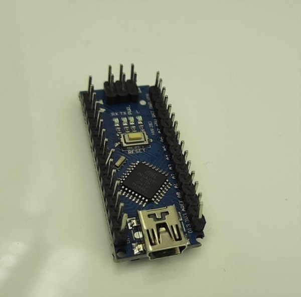
1.Arduino Nano – 1 Nos
2. Joystick Module – 2 Nos
3. Servo Motor (180 degree) – 4 Nos
4. Male to Female Jumper Wire – As per Required
5. Male to Male Jumper Wire – As per Required
6. Dc Shaft Motor – 2 Nos
7. Push Button – 2 Nos
8. Mini Bread board
9. Power Supply – 5 V 1 Amps
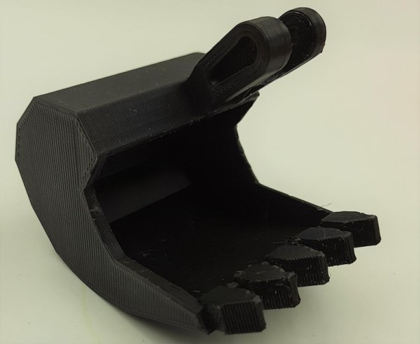
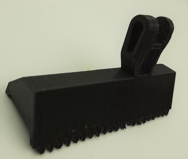
Step 3: 3D Parts
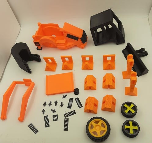
These are the 3D Assembly Parts for JCB.
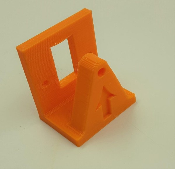
Step 4: Start With Physical Building – Servo Motor 1
First fix the arm with the attaching part in a corresponding slot using Fevikwik.
Then Place the Servo Motor into the base 3D Parts and screw it outside.
Now insert the attaching part in the middle of the Base 3D parts. Check Once attaching part will perfectly fix into the servo Motor shaft. Then only it can be able to move along with the Attaching part.
If it is not fixed properly the servo motor only rotates.
Step 5: Physical Building – Servo Motor 2
This is the Back side of the JCB. Fix the arm with the attaching part in a corresponding slot using Fevikwik.
Then Place the Servo Motor into the base 3D Parts and screw it outside.
Now insert the attaching part in the middle of the Base 3D parts. Check Once attaching part will perfectly fix into the servo Motor shaft. Then only it can be able to move along with the Attaching part.
If it is not fixed properly the servo motor only rotates.
Step 6: Physical Building – Servo Motor 3
Just continue the same procedure. Here we have to fix the gripper with particular slot. Check, the arm is properly fixed with the servo motor shaft.
Step 7: Physical Building – Servo Motor 4
This is the front part of the JCB. we have to fix the arm with gripper with particular slot. Check, the arm is properly fixed with the servo motor shaft. Now it is able to rotate from top to bottom.
Source: JCB Machine
- What is a JCB machine known as?
A JCB is also known as the backhoe loader. - How many Joystick Modules are required for this project?
Two Joystick Modules are required. - Can this model lift heavy weight like real construction equipment?
The article states that real JCB machines can lift heavy weights, but it does not specify the lifting capacity of this specific model. - What adhesive is used to fix the arm with the attaching part?
Fevikwik is used to fix the arm with the attaching part in the corresponding slot. - Why must the attaching part be fixed perfectly into the servo motor shaft?
If it is not fixed properly, the servo motor will only rotate without moving the attaching part along with it. - What is the power supply requirement for this project?
The project requires a 5 V 1 Amps Power Supply. - How many Servo Motors are used in total?
Four Servo Motors are used in the project. - What happens if the arm is not properly fixed with the servo motor shaft?
If not fixed properly, the servo motor only rotates instead of moving the attached mechanism.