Contents
- 1 Team Members
- 2 Mentor
- 3 Introduction
- 4 Components Used
- 5 Idea
- 6 Arduino Uno Board (ATMega328P)
- 7 Approach to Project
- 8 Sound Synthesis
- 9 Working Code
- 10 Expenses Incurred
- 11 Links
- 12 Videos
Team Members
Sumeet Fefar
Ashwin Kachhara
Prakhar Khandelwal
Nachiket Deo
Samitinjay Patil
Mentor
Hemant Ranvir
Introduction
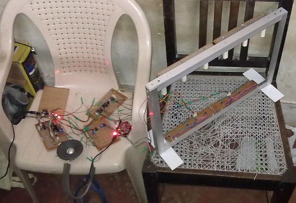
We have created a harp without strings i.e. IR sensor-receiver pairs function as strings in our device. The device senses when a string is being plucked (causes blockage of IR). Correspondingly, the particular sound is produced by Direct Digital Synthesis.
Components Used
- TSOP 1738 sensors
- IR Leds
- DM7474 D Flip-Flops
- LM 555 Timer
- Arduino Uno (Atmega 328P microcontroller)
- TIP 122 Darlington Pair Transistor
- BC 547 Transistor
- 3.5mm Socket
- IC 7805 Voltage Regulator
- 12V, 1A Power Adapter
- LM 324 Op- Amps
- Switches
- Speaker
Idea
We used 6 TSOP sensors to identify the blockage of infrared led’s. They then give digital output to microcontroller which processes data and gives 6-bit digital output to Digital to Analog converter(r-2r ladder). DAC converts the digital input to analog data which is then filtered and amplified to drive the speakers.
Arduino Uno Board (ATMega328P)
The microcontroller is used to interpret the sensor data and output the stored waveforms at the frequency assigned to the plucked strings using an interrupt.
Sensor input pins (pins A0 to A5 on Arduino i.e. PORTC)are marked in red.
DAC output pins (digital pins 8-13 i.e. PORTB)are marked in green.
The blue-marked pins (digital pins 3-7)connect to the buttons used for tone selection.
The yellow marked pin(digital pin 2) is used to clear the flip-flops.
An 8-bit timer is used to run the interrupt that triggers writing of output on PORTB.
Approach to Project
Since we were somewhat familiar of sensors because of line follower competition, we knew that working with the photodiode sensors would be difficult as their alignment and low sensitivity were some of the major problems. So we found out TSOP sensors which gave excellent variation from 0.0 to 4.81 V. Then we worked with two sensors kept at a distance of 5 cm to test that one led is not interfering with another sensor. We used pipes to remove this problem.
TSOP sensors require the IR LED to operate on a square wave of a particular frequency, which in this case was ~38kHz. We provided the required square wave form by a circuit using the 555 timer.
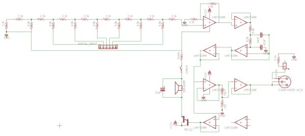
Schematic of the above circuit
We then used DAC0808 to convert the digital output of TSOP sensors into analog signal but it was not working as per our expectations so we designed our own DAC chip using r-2r ladder. We were then getting range from 0 to 4.5 V. Now we wanted to amplify this signal without affecting previous circuit. For this purpose we used a buffer and an amplifier which then gave range between 0 to 8.6 V. We then gave this output to speaker which we took out from synth. But we realised that the current was insufficient to drive the speaker, so we put a Darlington transistor(Tip122) whose current rating was 5A to drive the speaker. When we analysed the output on an oscilloscope, we found that the waveform was grainy. To smoothen the waveform, we used sallen-key low pass filter to remove high frequency noises.
Schematic of the DAC chip
While testing the sensitivity of the sensors, we realised that it was not responding to very quick flicks of fingers. To resolve this problem, we used D flip-flop IC 7474N as a memory to store even a single flick.
Flip-Flops chip
Schematic of the flip-flop chip
To get sound from earphones, we placed a 3.5 mm audio jack after the low pass filter. But to get 0 to 5V for the jack we placed a sort of buffer after the low pass filter with appropriate resistances to get the required output.
To power the circuit, we used a 12V, 1A adapter. Since we needed both 12 V and 5V supply we used LM7805 to get 5V supply. We also provided switches for the power supply and for switching between audio jack and speaker. Capacitors ensure security to LM7805 when a large sudden change in voltage occurs during Power OFF-ON toggle.
Power Circuit
Schematic of the above circuit
Sound Synthesis
To generate a sine wave signal from a microcontroller, we must write the values in digital form, with particular delay time between, onto any set of pins. To do this, we stored the sampled values of the signal in an array. There are two ways to provide the above mentioned delay:
Delay()
One is to use the delay() function of Arduino, with argument corresponding to the required frequency, between the values. This is a highly inefficient method which does not utilise the full processing power.
Interrupts
The other method is the use of Interrupts and this is what we have used. We have used an interrupt of prescalar 8 to increment a 32-bit accumulator, whenever it is called. Thus we are not putting the processor in a state of sleep between writing of the values and hence it is free to do other processing ex. processing of input. We can vary the frequency of the output by changing the increment value. A larger increment will produce a higher increment . The increment is calculated by this formula
For more detail: IR Harp