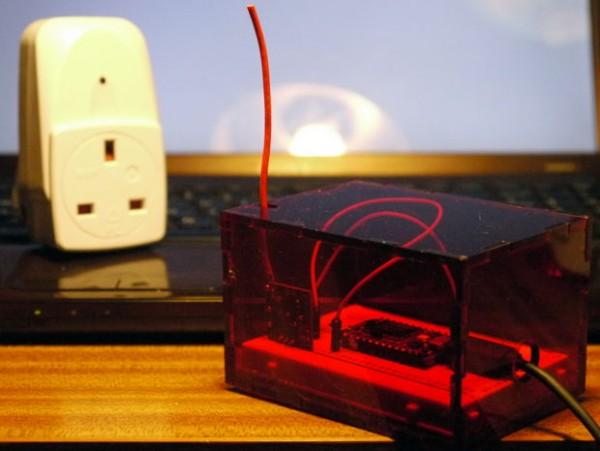
This is a very low cost and basic from of home automation allowing you to turn on and off lights and other devices using your computer or mobile phone.
It has been built and tested use using UK power plugs, but the same protocol is used on many budget remote power switchers from around the world.
Step 1: What You Will Need
You will need…
- A Spark Core wi-fi development kit
- A remote controlled mains sockets set *
- A 433MHz Transmitter Module **
- A short length of wire (>9cm)
- 3 Jumper wires
- A 5V PSU and USB cable ***
- A web server with PHP installed (optional)
…and the following tools…
- A soldering iron (and some solder)
- Wire cutters and strippers
- A computer with Internet access
…and if you want to build the red box (totally optional) you will also require…
- A laser cutter or laser cutting service
- Contact glue
- Feet / pads (even more optional than the rest)
* As a rule of thumb if the pack contains 3 sockets and is the cheapest in the shop, if the remote control can be set to 1 of 4 “groups” or “channels”, and and if the remote control has on and off buttons for 3 or 4 devices, then the odds are it will be compatible. Unfortunately the protocol used does not have a global name and you will not find anything printed on the packaging to say the sockets are compatible. I have use sockets purchased from Clas Ohlson (now replaced by a new set that I have not tested) and friends have used sockets for clearance shops and from Maplin (although this is the more costly option).
** The transmitter module is normally available thought ebay for under £1 sterling and under $1 US, or slightly more if you want a quick delivery.
*** The Spark Core comes with a very short power cable and you may be able to power it from another device such as a network router.
Step 2: Construct the Antenna
The first task is to attach an antenna to the transmitter module. This requires some basic soldering. If you know what you are doing just solder exactly 87mm of wire on to “Ant” on the module and move on to the next step.
If you have never soldered before then you can absolutely still do this. I recommend following an online tutorial and having a practice fist, and then coming back here.
The antenna should be 87mm long. Making it longer does not make the signal better unless it is an “Harmonic” of the base wavelength. I have a blog post with the antenna lengths you can use and a little of the maths behind working that out.
After measuring, cutting and stripping the wire you will need to tin the end of it. Also add just a little solder of the “Ant” point on the module. Place the antenna on the “Ant” point, heat them with the soldering iron, wait until they meld together, remove the soldering iron, hold it still until the solder solidifies, and you are done.
For more detail: Internet Controlled Mains Switcher

