Summary of Improved Artwork Clock
This article details a DIY project to build an interactive artwork clock using an Arduino Nano, an RTC module, and LEDs. The clock displays time via 7-segment digits on an MDF panel with a wood veneer overlay, activated by sound or buttons. It uses transistors to manage LED segments for a persistence-of-vision effect, allowing the user to impress custom images onto the wooden surface.
Parts used in the Improved Artwork Clock:
- Arduino Nano (or clone)
- Real Time Clock RTC DS3231
- Sound detector
- 100 x 5mm white LEDs (84 used)
- 11 x NPN transistors TO-92 2n2222A
- 30 x 22 Ohm resistors
- 10 x 4.7kOhm resistors
- 3 Buttons
- 1 Switch
- 2 x 3.7V batteries with case
- 5m wire
- MDF panel (approx. 50x50cm)
- Wood veener (50x25cm)
- White wood paint
- Laser printer paper and acetone
- Wood glue and paint brush
- Hot glue pistol
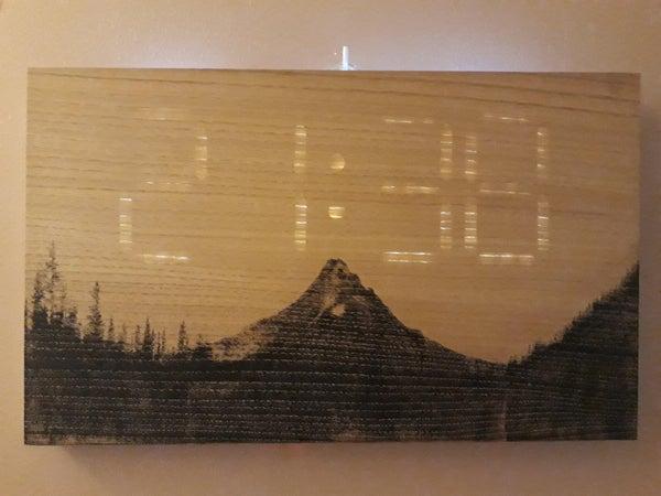
Want to improved some piece of artwork? Surprise your friends by showing day time through it!
You will find in this instructables the way of making the same clock I did, it can totally be improved with strip leds, 3d printed supports, painting skill and any other thing you will be able to imagine!
Supplies
ELECTRONICS
– 1 arduino nano (or clone)
– 1 Real Time Clock RTC DS3231
– 1 sound detector (like this)
– 100 hundred 5mm white leds (84 in use)
– 11 NPN transistors TO-92 2n2222A
– 30 x 22 Ohm resistors
– 10 x 4,7kOhm resistors
– 3 buttons
– 1 switch
– 2 x 3,7V batteries with case
– 5m wire (I had a bobine for ground wire so I used it)
MATERIALS
– 1 MDF pannel about 50x50cm
– 1 wood veener (I chose chataignier wood 50x25cm has it could be found in France here)
– White wood paint
– A laser printer and acétone if you want to impress a printed picture
– Wood glue and paint brush
– hot glue pistolet to fix leds
Step 1: How Does It Work?
This 7 segments clock work with 11 NPN transistors managing the led enlightment :
7 transitors to choose which segment is to be enlightened
4 transistors to choose on which digit the segment is to be enlightened
As we will use a loop to sweep each digit separetly, there will be tthe illusion of full enlightment thanks to retinal persistence.
As exemple, to display the time 12:34, the sequence will be : 12:34 -> 12:34 ->12:34 -> 12:34.
Once the clock is able to display time, we will set another loop to maintain the display for about 10s and then we will update time by reading RTC.
This loop is lunched after the sound detector set the information of time display to ON and is maintained for about 5 minutes.
Some buttons are also set in If conditions in order to be able to set time (which you’ll have to do twice a year at least on local time change)
Step 2: Making Your Art Support
First thing first, you have to make the support for your wooden veener and for all the electronic.
I chose dimensions regarding wood veener in order not to cut it but this can be done easily. Mine is 50x25cm, I cut it through the mdf panel and also the 2 side supports which are 25x3cm (you can make them wider if you want to be sure that wire and electronics don’t touch the wall while the clock is hung on it).
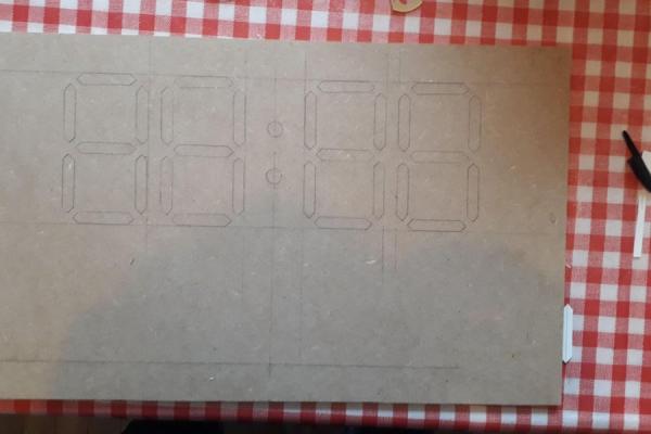
After, you have to draw the digits and cut them through the panel. I chose to set 3 leds by segments so each segment is 10mm wide and 50mm high (the both end are 5mm high). I set it in the third top of the panel. You can check my drawing for better understanding and distance between each element.
Make a hole through each segment, which means 30 ones counting the 2 central dots. It has to be wider than your saw. Then saw each digit, it take some time but if you go carefully result will be nicer.
You can now glue the side support and then the main support is made!
Electronic support :
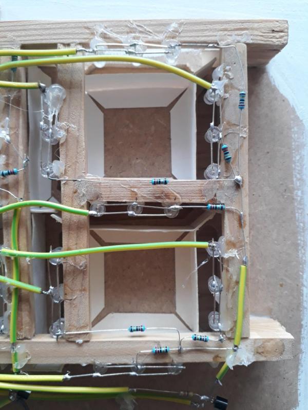
Since I didn’t have 3d printer, I chose to make the electronic support with wood scrap and the light barrier with paper (in order to enlight only one segment). I made it in order to be able to glue led directly in front of each segment and approximately 2cm away from the side of the panel. I glued every piece of wood and then glued the whole support on the panel, after gluing paper barrier.
I ended this part with a button and sound detector support you can glue anywhere you want!
Also the fixation to hung the clock on the wall can be made with 2 mdf blocks glued on the main panel with a screw in each.
I tried to add as many explanation pictures as possible. Now your support is ready to receive the electronic parts!
Step 3: Improved It With Your Nano
Your project will now become a clock while we will add arduino and electronics.
First, you have to prepare each led segment with 3 leds set in row (plus on plus and minus on minus). I chose this solution in order not to have a to high tension for the batteries. Just bend each part at 90° and solder it to the next led. You will have 3 leds in rows, repeat the operation for each other segment.
I strongly recommend you to try every set of 3 leds in order to be sure that everything is okay before continuing.
Now, you have to glue it on the support you made, I chose to put the arduino on the left of the panel and when I installed the led, I put the plus side on the top for horizontal segment and on the left for vertical segment. This will make the wiring easier. Try to put glue only on the sides of leds in order not to block light.
Now, for each 3 led set for each digit, we will solder a 22 Ohm resistor in order for the led not to consume to much electricity, and then solder every minus together.
Then we will set transistor which will be used to display time. First, for the digit on the left, you will solder one transistor emitter on each plus of each segment, these will permit to choose the digit to show. I recommend you to bend the middle leg (base) since we will solder a resistor after.
You can now set a transistor collector on each digit on the minus which you soldered together just before. You have 4 transistors to add, soldering it on collector leg.
Now solder a 4,7kOhm resistor on each base leg (the middle one) of each transistor.
For better understanding of transistor, you can look here.
Wiring :
Since all the digit will receive tension when you want to enlight one segment, we have to wire them together. Now you will connect each same + segment of each digit together. Just cut the wire at correct length and solder it, it take some time but the work is not so hard.
I chose to connect the 2 leds of the dots with a and b segment, since there is always one of them that is enlightened.
You can try each segment with the battery in order to be sure that the wiring is correct.
Before wiring the Nano card, you have to set every power supplies and ground for each element needing it : RTC, sound detector, nano card, and led.
For led, you have to put power supply on each of 7 transistor collector leg (which will bring the power when the base will be set to 1). The emitter leg is connected to the leds. You have to do the same for ground for the 4 transistors managing the digit, connecting it to the emitter legs.
Now you have wire every elements to the nano card, I soldered it directly to the card but you can use plugs. You can find after which pin is to be connected on which elements:
Microphone entry -> Pin 14
SDA on pin A4 and SCL on pin A5 for RTC
A segment on pin D2
B segment on pin D3
C segment on pin D4
D segment on pin D5
E segment on pin D6
F segment on pin D7
G segment on pin D8
(check segment determination here)
1st digit minus on pin D9
2nd digit minus on pin D10
3rd digit minus on pin D11
4th digit minus on pin D12
Buttons on pins 15, 16 and 17 (you have to put a 4,7kOhms resistor in parallel of each button in order for the card to be able to measure a tension).
I give you my wiring, but you can do it has you prefer but you will have to modify the code.
While everything is wired, you can upload code as usual, you will have to had the library needed for this code (TimeLib.h, DS1307RTC.h, Wire.h).
The code is at the end of this step.
If you want to modify sensibility of sound detector, you can increase value in the if loop : valeurSON > 1.
The button will be used to set the time :
– push on both button 1 and 2
– set time with these 2 buttons
– when you have set the correct time, push on the third button to fix the time.
Step 4: Make It Visual
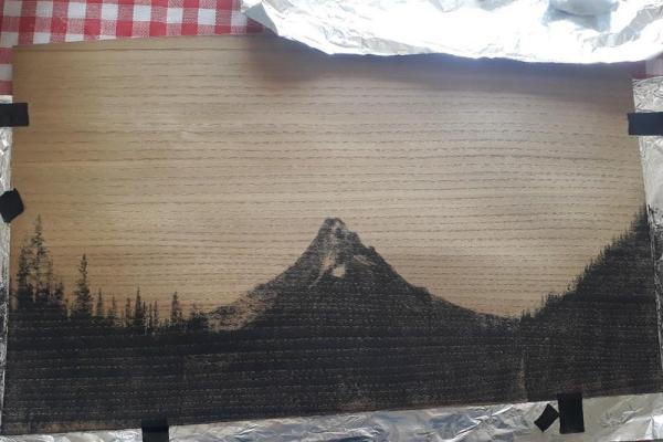
You have been through hard work, the last but not least step is coming. I chose to impress black and white picture with acetone but you can totally make your own piece of artwork if you have that kind of skill (which I don’t).
For the wooden layer, you have to be very carreful in order not to damage it and to keep it flat. I press it under some big books in this way (it seems that this kind of wood layer could be flaten using water or alcohol).
I printed 2 times on each of paper in order to be sure that impression will be correct. Anyway, I had to do it twice since the first impression was not enough dark in my way (you can see the difference on pictures).
Use a cloth rag for better results.
When your veener is ready you have to carrefully glue it on the main panel, starting with puting glue on the mdf panel with a brush stick and avoiding to set glue on the segment, else glue drops could be seen when light will be turned on.
Greetings, you have now a nice clock of your own!
Step 5: Further Ideas
As satisfying as this project has been, here are some improvment that would make it even nicer :
– addind strip leds in order to make the brightness brighter and the management easier
– 3d printing your support for electronic stuff on the back in order to make it easier and faster to make
Source: Improved Artwork Clock
- How does the clock display time without all lights being on?
The clock uses a loop to sweep each digit separately, creating the illusion of full enlightenment through retinal persistence. - Can I improve the brightness of the clock?
Yes, adding strip LEDs is suggested to make the brightness brighter and management easier. - What is the best way to fix the time on the clock?
Push both button 1 and 2 to set the time, then push the third button to fix it once correct. - Does the clock require a computer to run after assembly?
No, it runs on 3.7V batteries, though code upload requires connecting to a computer initially. - How do I activate the time display?
A sound detector sets the information of time display to ON, maintaining the loop for about 5 minutes. - What library files are needed for the code?
You must add TimeLib.h, DS1307RTC.h, and Wire.h libraries to the code. - How should I prepare the wooden layer for the image?
Print the image twice on paper to ensure darkness, then use acetone to impress it onto the wood veener. - Is it possible to change the sensitivity of the sound detector?
Yes, you can increase the value in the if loop where valeurSON is checked.