Summary of Importance of Sensors in Robotics and Interfacing with Arduino
Summary: This article explains connecting simple touch (leaf) switches and light sensors (photoresistors) to an Arduino-based two-wheeled ArdBot. It covers wiring, mounting, example Arduino sketches for bump (polling and interrupt versions), debouncing considerations, using multiple switches (and shift registers), and steering with two photocells and a flashlight, including suggested resistor choices and threshold/ambient values.
Parts used in the ArdBot:
- Arduino Uno (or compatible microcontroller)
- ArdBot two-wheeled chassis (plastic or aircraft-grade plywood)
- R/C servo motors (left and right)
- Solderless breadboard (170 tie point)
- Leaf switches (bump switches, microswitch style)
- Wires and separable male header connectors
- 10 kΩ pull-down resistors for switches
- Photoresistors / photocells (CdS cells)
- Series resistor for photocell voltage divider (example 10 kΩ)
- Mounting hardware (screws, brackets, PVC mounts, adhesives)
- Optional: PISO shift register (74HC165 or CD4021) for many switches
- Flashlight (for light steering demo)
Sensors are essential for the functioning of senses. Within the field of robotics, the fundamental senses rely on basic sensors, such as mechanical switches that detect object contact, and photosensitive resistors and transistors that identify the presence or absence of light. Remarkably, a robot can accomplish significant tasks with just touch and rudimentary vision. In this month’s segment, you will gain insight into linking switches and photosensors to the Arduino platform. You will also discover how to harness the data offered by these sensors to actively control a robot’s motors. These components form the core foundational elements for almost any autonomous robot you create. Once you master the utilization of these sensors to execute your commands, you can deploy them in a wide array of applications.
Arduino Robotics:
What We’ve Covered So Far
This piece of writing extends the foundation established in prior sections of this series, which predominantly focuses on creating and utilizing the ArdBot (refer to Figure 1). The ArdBot is an economical two-wheeled robot with differential steering, designed around the widely used Arduino Uno and compatible microcontrollers. If you wish to actively engage with the content, it’s advisable to explore the preceding three episodes. This will ensure you have a good grasp of the storyline and characters involved.
In the initial segment, Part 1, we presented the ArdBot project alongside the Arduino platform, as well as the fundamental principles of programming for this robust controller.
Part 2 provided an elaborate explanation of how to assemble the ArdBot, utilizing readily available materials like plastic or aircraft-grade plywood. Moving on to Part 3, a deeper exploration of the Arduino was undertaken, delving into the intricacies of programming R/C servo motors using this platform.
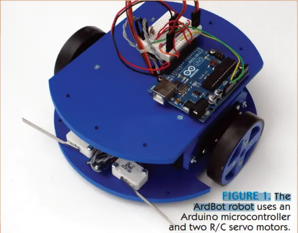
The concepts discussed here are applicable to a wide range of robots employing the Arduino microcontroller, and which are propelled by two motors and move on wheels or tracks. You have the flexibility to customize the methods and programming code for the specific robots you are developing. The ArdBot serves as a foundation for further expansion, while also embodying the archetype of a standard desktop-sized robot.
The realm of sensors is quite intricate, encompassing a breadth of captivating aspects that can’t be fully addressed within a single article. Therefore, in the upcoming month’s installment, you will delve into additional categories of cost-effective sensors that can be integrated with your ArdBot (or any other robotic project).
Getting in Touch With Your Robot
Sensors, whether found within humans or robots, are engineered to generate a response. The nature of this response hinges on the specific type and quantity of the sensation. Interpretations are significant. For instance, a gentle summer breeze is typically perceived as pleasant. However, when the air pressure escalates to hurricane levels and the temperature plummets below freezing, those same sensations elicit considerably adverse reactions.
Touch, often referred to as tactile feedback, represents a basic form of responsive sensation. The robot comprehends its surroundings by initiating physical interaction, which is detected through an array of touch sensors. The outcome of such interaction is entirely governed by the programming you implement within your robotic system.
Frequently, encountering an object leads to a state of alertness. Consequently, the robot’s response involves halting its ongoing activities and retreating from the situation. In alternate scenarios, contact could signify that your robot has reached its designated home base or has identified an adversary robot, signaling an impending engagement.
The humble mechanical switch stands as the most prevalent and uncomplicated variation of a tactile (touch) feedback mechanism. Virtually any transient, spring-loaded switch is suitable. Upon the robot’s contact, the switch comes together, thereby establishing a circuit connection.
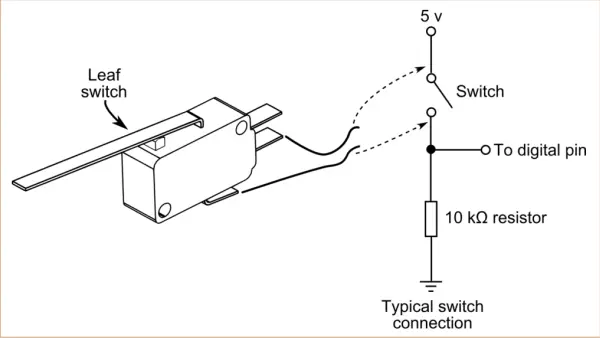
I prefer employing leaf switches (refer to Figure 2), as they operate in a manner reminiscent of a cat’s whiskers. Although occasionally termed “microswitches” due to a prominent brand, I’ll use the term “leaf switches” to prevent any ambiguity. Irrespective of the manufacturer or version, they are generally simple to install and often include plastic or metal strips of varying lengths that amplify the switch’s sensitivity.
It’s possible to increase the surface area of contact for the leaf switch by affixing larger sections of plastic or metal through adhesive or soldering. As an illustration, you can take sturdy music wire (readily obtainable at hardware stores) or repurpose an inexpensive wire clothes hanger. By shaping it creatively, you can enhance the contact area.
You can solder the end(s) onto the leaf. Alternatively, opt for slender segments of wood, plastic, or metal. However, ensure that the added weight of the extension doesn’t inadvertently trigger the switch. Preventing false alarms is crucial.
The switch can be linked either directly to a motor or, more frequently, to a microcontroller. A standard wiring diagram for the switch is depicted in Figure 2. The inclusion of a 10 kΩ pull-down resistor serves the purpose of maintaining a consistent digital LOW (0 volts) output for the switch in the absence of contact. Upon contact, the switch is engaged, resulting in an elevated output that generally reads around five volts, as illustrated here.
Using Leaf Switches as Bumpers
By installing two conventional leaf switches on the front of your ArdBot, it becomes capable of sensing collisions. When positioned on the sides, these switches enable your robot to ascertain whether the encountered object is located to the left or right, subsequently allowing it to navigate around the obstacle.
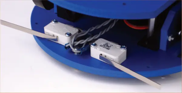
Figure 3 depicts a set of leaf switches affixed to the front of the ArdBot, resembling bumpers. These types of switches can be readily found on various online electronics stores and are frequently encountered as surplus items.
I haven’t expanded the switches’ contact area deliberately, as my main focus is to showcase the underlying concepts. Feel free to employ your creativity to improve the switches for achieving the desired level of sensory detection. For instance, it’s immediately noticeable that the robot might not detect small objects positioned right between the switches. To address this, you can either enlarge the contact area or opt for an alternative method of “sensing” to prevent collisions proactively.
For attaching each switch, locate two appropriate holes in the robot’s base or create new holes through drilling. Leaf switches typically come with three terminals: common, normally open (NO), and normally closed (NC). Connect the common and NO terminals with wiring. If space is constrained, you can remove the NC connection to create additional room.
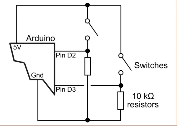
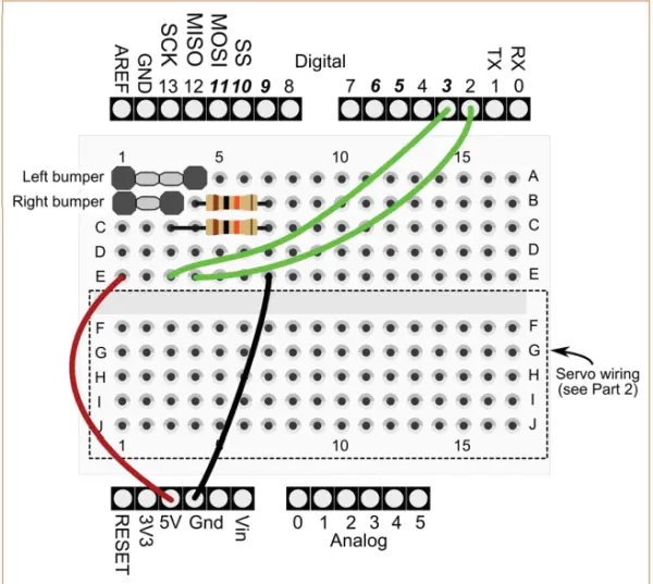
In Figure 4, you can observe the schematic illustrating the linkage of the two switches to the Arduino’s digital pins D2 and D3. Figure 5 presents the identical circuit configuration, depicted in a breadboard perspective. Utilize the upper section of the ArdBot’s 170 tie point solderless breadboard for this purpose. Keep in mind that the lower half of the breadboard is already allocated to the ArdBot’s servo wiring, as elaborated in Part 2 of this series.
In the initial model, I fashioned connectors for the switches by soldering two wires onto the pins of a separable male header. These headers permit you to detach the required number of pins for your purpose. In one instance, I adjusted a connector to span three pins in width, eliminating the central pin. Subsequently, I soldered the switch wires to the outer pair of pins. For the other connector, I tailored it to encompass four pins in width, eliminating the two central pins. The manner in which these two connectors are inserted into the breadboard can be observed in Figure 5.
Crucial! Ensure that all wires and additional components are securely inserted into their respective timepoint sockets on the breadboard. Unstable connections rank as the second most prevalent factor leading to issues while utilizing a solderless breadboard; the primary cause is typically misplacing wire connections into incorrect tie points!
The demo program “bumper.pde” is displayed in Listing 1. The ArdBot initiates forward movement until either of its front bumper switches comes into contact with an object. As soon as the switch is activated, the robot promptly shifts into reverse, followed by executing a turn in the opposite direction of the obstacle. The time intervals are denoted in milliseconds: a 500-millisecond (half-second) reversal period and a 1,500-millisecond (1.5-second) spinning movement to the right or left.
/*
ArdBot bumper switch demo
Requires Arduino IDE version 0017
or later (0019 or later preferred)
*/
#include <Servo.h>
const int ledPin = 13; // Built-in LED
const int bumpLeft = 2; // Left bumper pin 2
const int bumpRight = 3; // Left bumper pin 3
int pbLeft = 0; // Var for left bump
int pbRight = 0; // Var for left bump
Servo servoLeft; // Define left servo
Servo servoRight; // Define right servo
void setup() {
servoLeft.attach(10); // Left servo pin D10
servoRight.attach(9); // Right servo pin D9
// Set pin modes
pinMode(bumpLeft, INPUT);
pinMode(bumpRight, INPUT);
pinMode(ledPin, OUTPUT);
}
void loop() {
forward(); // Start forward
// Test bumper switches
pbLeft = digitalRead(bumpLeft);
pbRight = digitalRead(bumpRight);
// Show LED indicator
showLED();
// If left bumper hit
if (pbLeft == HIGH) {
reverse();
delay(500);
turnRight();
delay(1500);
}
// If right bumper hit
if (pbRight == HIGH) {
reverse();
delay(500);
turnLeft();
delay(1500);
}
}
// Motion routines
void forward() {
servoLeft.write(180);
servoRight.write(0);
}
void reverse() {
servoLeft.write(0);
servoRight.write(180);
}
void turnRight() {
servoLeft.write(180);
servoRight.write(180);
}
void turnLeft() {
servoLeft.write(0);
servoRight.write(0);
}
void stopRobot() {
servoLeft.write(90);
servoRight.write(90);
}
void showLED() {
// Show LED if a bumper is hit
if (pbRight == HIGH || pbLeft == HIGH) {
// Turn LED on
digitalWrite(ledPin, HIGH);
}
else {
// Turn LED off
digitalWrite(ledPin, LOW);
}
}
Feel free to explore different delay configurations based on your robot’s speed characteristics. In cases where you’re using swifter servo motors, opting for a briefer delay is viable. The concept revolves around rotating the robot by approximately one-quarter to one-half turn, effectively guiding it away from the obstacle.
Take note that terms like “left,” “right,” “front,” and “back” are somewhat context-dependent in the context of a robot like the ArdBot. The orientation of the front end is not fixed, allowing for flexibility in defining left and right directions. In my prototype, I positioned the two leaf switches on the end that had more available mounting space, effectively designating that end as the “front.” The coding within bumper.pde is tailored to this design decision. If your robot exhibits behavior contrary to your expectations, you can interchange the values in the motion routines (such as forward, reverse, etc.). For more comprehensive insights into the servo commands’ functionalities and operations, refer to Part 3 of this series.
Understanding the bumper.pde Sketch
Like all Arduino sketches, bumper.pde is structured into three main sections: declaration, the setup() function, and the loop() function.
The initial section at the beginning of the sketch establishes the variables employed across the program. It additionally initializes two instances of the servo class. As you’ve learned from Part 3 of Making Robots with the Arduino, the servo class is included as a library within the Arduino programming toolkit. It’s utilized for managing one or multiple R/C servos. The declaration also designates the two leaf switches as linked to digital pins D2 and D3, along with the utilization of the Arduino’s internal LED (linked to pin D13) for visual indication.
Within the setup() function, the servos are configured to be associated with digital pins D9 and D10. Furthermore, the pins allocated for the LED and the two switches are designated as outputs and inputs, respectively.
The central segment of the sketch resides in the loop() function, which continues in an endless loop. It initiates by engaging the two servos to propel the robot in a forward direction. Subsequently, the sketch employs the digital Read statement to capture the present condition of the two switches. The real-time status of the switches is retained in a duo of variables (pbLeft and pbRight — the pb signifying pushbutton). These variables find application in various other parts of the sketch.
The focal point within the loop() function revolves around the pair of if statements. Here is the statement responsible for assessing the left leaf switch:
if (pbLeft == HIGH)
reverse();
delay(500);
turnRight();
delay(1500);
}
The condition “pbLeft == HIGH” examines whether the value stored in the pbLeft variable (previously determined according to the state of the left leaf switch) is set to HIGH. If it is, this signifies that the left switch is engaged, indicating the robot has encountered an obstacle. Conversely, if the value is LOW, this indicates that the switch is disengaged, and the robot proceeds with its movement.
The bumper.pde sketch encompasses several functions created by the user. The majority of these, such as forward() and reverse(), pertain to controlling the servo motors. Another function, depicted as shownLED(), alternates the state of the LED linked to pin D13 on the Arduino, switching it on or off in response to the state of a switch. Employ this as a visual cue to confirm the proper functionality of the programming code.
Switch Triggers Using Polling or Interrupts
The coding within bumper.pde utilizes a technique referred to as polling. The sketch consistently monitors the condition of the two switches. When a switch is pressed, its state changes from LOW to HIGH. When in the HIGH state, the robot is directed to alter its course. These switches are checked or polled numerous times every second.
Polling is considered appropriate when dealing with straightforward sketches and minimal demands on the Arduino’s resources. However, for code that places a higher load on processing, there exists a slight possibility that the controller might overlook the closure of a leaf switch. It could be engaged in other tasks between polling intervals, remaining oblivious to any events occurring during those intervals.
In reality, even with a moderately intricate sketch, you can achieve a detection rate of approximately 99 percent for switch closures. This is due to the fact that, from the perspective of a microcontroller, switch closures tend to endure as relatively extended periods of time. Even a momentary 100-millisecond (one-tenth of a second) contact becomes considerably lengthy for a microcontroller operating at 16 MHz. Consequently, it’s highly probable that the switch closure will be successfully recognized.
However, if it’s absolutely crucial to ensure the detection of even the most momentary contact, you might want to contemplate the utilization of hardware interrupts as opposed to polling. Through an interrupt, specialized code is executed solely when a precise external event transpires. This approach is advantageous as the main program loop() is no longer required to consistently monitor the pin states, thus allowing the controller to allocate resources to other tasks. Interrupt response time is measured in microsecond intervals, even if the Arduino is engaged in concurrent activities. (Although this isn’t invariably the case, contingent on the utilization of other hardware components on the controller. Nevertheless, any additional delay is typically minimal.)
The Arduino Uno is equipped with two internal hardware interrupts (while the Arduino Mega supports six), linked directly to digital pins D2 and D3. These pins are the ones to which the leaf switches are already connected, meaning that only a software modification is necessary.
For the interrupt implementation, refer to Listing 2 in interrupt.pde. In this version, the bumper.pde sketch has been adapted to actively monitor alterations in state on both of the hardware interrupts using the following instructions:
attachInterrupt(0, hitLeft, RISING);
attachInterrupt(1, hitRight, RISING);
/*
ArdBot interrupt bumper demo Requires Arduino IDE version 0017
or later (0019 or later preferred)*/
#include <Servo.h>
const int ledPin = 13;
const int bumpLeft = 2;
const int bumpRight = 3;
int pbLeft = 0;
int pbRight = 0;
Servo servoLeft;
Servo servoRight;
void setup() {
servoLeft.attach(10);
servoRight.attach(9);
// Set pin modes
pinMode(bumpLeft, INPUT);
pinMode(bumpRight, INPUT);
pinMode(ledPin, OUTPUT);
// Set up interrupts
attachInterrupt(0, hitLeft, RISING);
attachInterrupt(1, hitRight, RISING);
}
void loop() {
forward(); // Start forward
showLED(); // Show LED indicator
// If left bumper hit
if (pbLeft == HIGH) {
reverse();
delay(500);
turnRight();
delay(1500);
pbLeft = LOW;
}
// If right bumper hit
if (pbRight == HIGH) {
reverse();
delay(500);
turnLeft();
delay(1500);
pbRight = LOW;
}
}
// Motion routines
void forward() {
servoLeft.write(180);
servoRight.write(0);
}
void reverse() {
servoLeft.write(0);
servoRight.write(180);
}
void turnRight() {
servoLeft.write(180);
servoRight.write(180);
}
void turnLeft() {
servoLeft.write(0);
servoRight.write(0);
}
void stopRobot() {
servoLeft.write(90);
servoRight.write(90);
}
void showLED() {
// Show LED if a bumper is hit
if (pbRight == HIGH || pbLeft == HIGH) {
digitalWrite(ledPin, HIGH);
}
else {
digitalWrite(ledPin, LOW);
}
}
// Interrupt handlers
void hitLeft() {
pbLeft = HIGH;
}
void hitRight() {
pbRight = HIGH;
}
Take notice that the interrupts are labeled as 0 and 1, which correspond to pins D2 and D3 accordingly. The designations “hit Left” and “hit Right” denote the functions that are invoked upon the activation of the interrupt. Lastly, “RISING” is a predefined constant instructing the Arduino to initiate the interrupt when there is a transition from LOW to HIGH signal. Such a transition arises when the switch is engaged.
Both “hit Left” and “hit Right” elevate their respective “pb” variables to the HIGH state. Subsequently, the program promptly exits the interrupt handler. During the subsequent iteration of the Arduino’s loop(), it recognizes the elevated pushbutton state and executes the required obstacle evasion procedure. (Additionally, it’s important to observe that the pushbutton value is intentionally reset to LOW, in preparation for the forthcoming collision event.)
You could be wondering why the code governing servo control isn’t placed within the interrupt handlers. The rationale behind this is as follows: the delay statement, which is employed to guide the robot around an obstacle, becomes inactive within an interrupt context. Furthermore, it’s generally advisable to refrain from incorporating time-consuming operations within interrupt handlers.
To Let Bounce or Debounce?
In an ideal scenario, mechanical switches would generate precise and dependable digital signals for our microcontrollers. However, reality isn’t flawless, and we encounter an issue known as switch bounce. Instead of obtaining a neat LOW-to-HIGH digital transition when a switch is engaged, we observe five, 10, or even numerous erratic fluctuations, resulting from the movement of the metal contacts within the switch as they settle into place. This entire process occurs at a rapid pace, often taking just a few milliseconds.
In certain scenarios, it becomes imperative to eliminate the output fluctuations of a switch through a process called debouncing. Through debouncing, all the erratic fluctuations are smoothed out, resulting in a single, clean signal pulse that the microcontroller requires. Debouncing can be achieved through additional hardware components: a capacitor and a resistor form an RC network that introduces a delay in the switch signal’s rise and fall, effectively eliminating the glitches. Alternatively, debouncing can also be implemented through software by employing delays, ensuring that the microcontroller only registers the initial signal transition while disregarding subsequent fluctuations.
Neither the bumper.pde nor the interrupt.pde illustrations explicitly incorporate switch debouncing. Software delays are inherently embedded within the code, and the relatively sluggish nature of R/C servos negates the necessity for swift reaction times, rendering bounce-related issues inconsequential. Servos are directed within 20-millisecond intervals referred to as “frames,” meaning their functioning is refreshed approximately every 20 milliseconds. Interestingly, this aligns with the most pessimistic scenario of bounce glitches stemming from the majority of switches. Consequently, even when a switch experiences vigorous bouncing, its impact on servo operations remains minimal to non-existent.
If the requirement arises to debounce your switch inputs, you can access a distinct class library that can be downloaded and integrated into your Arduino setup. This library, known as “Bounce,” is accessible through the primary Arduino language reference resources. Additionally, the Arduino programming IDE includes a Debounce code example as part of its offerings.
Mounting Alternatives, More Switches
Before proceeding further, a couple of brief points to highlight. Up to this point, the discussion has centered on the two switches located at the robot’s front, on the right and left sides. However, you are welcome to position switches according to your preferences. For instance, you might opt for front and back switches or even deploy an array of switches encircling the robot’s periphery.
In the event that you incorporate more than two switches, you will need to resort to polling since only two pins can accommodate hardware interrupts (specifically on the Arduino Uno). In cases where you involve more than four or five switches, you might consider employing a different strategy.
In the scenario where you incorporate more than two switches, you will be compelled to rely on polling, as the Arduino Uno offers only two pins that support hardware interrupts. In the event that you intend to employ more than four or five switches, you might consider adopting a parallel-to-serial (PISO) shift register chip, like the 74HC165 or CD4021. These integrated circuits accept eight parallel inputs and furnish a serial data output that the Arduino can interpret. If, for instance, you are dealing with eight switches, the PISO mechanism trims down the number of required I/O pins from eight to three. An illustrative code example for this approach is accessible at arduino.cc/en/Tutorial/ShiftIn.
Let There Be Light (and let your ArdBot see it!)
Aside from tactile feedback, responding to light stands as one of the most prevalent sensory functions in robotics. When actual vision is not available, robots utilize electronic elements such as photoresistors and phototransistors that exhibit sensitivity to light. Your robot can be programmed to respond to either the mere presence or absence of light, or it might possess the capability to assess various aspects of light, such as brightness, color, or other qualitative attributes.
Photoresistors, often referred to as photocells, light-dependent resistors, or CdS cells (short for cadmium sulfide cells), are perhaps the most straightforward options for employing basic light sensors. The photocell operates as a resistor whose value undergoes alteration based on the intensity of light affecting its sensing surface. In situations of low light levels, the photocell exhibits high resistance, typically ranging from around 100 kΩ to over one megohm, dependent on the specific component. Conversely, as more light reaches the cell, its resistance diminishes. Under conditions of high illumination, the resistance can dwindle to as little as 1 kΩ to 10 kΩ.
The specific resistance values for darkness and light fluctuate based on the component and even within photocells of the identical brand and model. The usual tolerance for these values is around 10 to 20 percent. While you can acquire new photocells, they are frequently encountered in the surplus market. Opting for a collection of assorted units and utilizing a multimeter to assess each is recommended. Photocells that are cracked or damaged are no longer functional, and their sensing surfaces can deteriorate due to exposure to air and moisture, rendering them ineffective. Dispose of any photocells that fail to respond appropriately when near a desk lamp.
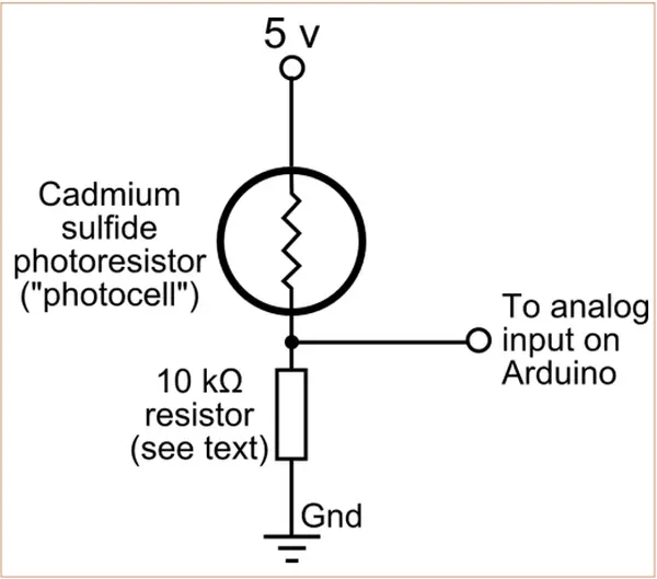
As a resistor, you can readily transform the output of a photocell into a fluctuating voltage by simply linking another resistor to it in a series configuration, as depicted in Figure 6. The choice of the series resistor’s value is contingent upon the dark/light resistance spectrum of the photocell and the intended application. For the photocells I employed, their dark resistance hovered around 40 kΩ, and their light resistance stood at 30 ohms. In situations of average room illumination, the cells correspondingly exhibited resistance in the vicinity of 10 kΩ. Consequently, I opted for a 10 kΩ series resistor.
The voltage at the junction between the photocell and the series resistor is determined by the ratio of their respective resistance values. When these two resistances are equal, the divided voltage between them equals half of the supply voltage. For instance, with a supply voltage of five volts under average room illumination, the resultant output voltage would be 2.5 volts.
Connect the signal point between the photocell and the series resistor to the A0 pin on your Arduino. Proceed to compile and upload the sketch, and subsequently, open the serial monitor window. A sequence of numbers will be displayed, aligning with the converted 10-bit (0 to 1023) numerical values of the sensor’s output voltage. In situations where all light to the photocell is obstructed, anticipate a low numeric reading, while under complete illumination, expect a higher numeric value.
Steering Your Robot With a Flashlight
With the application of two photocells positioned on either side of your ArdBot, you have the capability to guide it using a flashlight. In an environment with standard room lighting, the robot is programmed to halt, awaiting your instructions. Adjust the flashlight so that its light is distributed somewhat evenly over both photocells, and the robot will initiate forward movement. When the light intensity differs between the two cells, the robot will pivot toward the photocell that experiences a greater amount of light exposure.
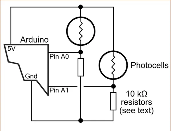
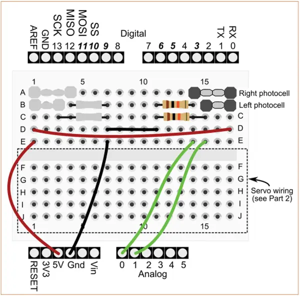
Consult Figure 7 for a diagram illustrating the configuration involving two photocells. Correspondingly, Figure 8 portrays the same circuit from a breadboard perspective. In my own prototype, I fashioned compact mounts for the photocells utilizing surplus PVC plastic, subsequently affixing these mounts to the top deck of the ArdBot using metallic brackets. The photocells I utilized had dimensions of 0.29″ x 0.25″ (elliptical shape). I drilled holes slightly smaller than the cell size, subsequently utilizing a rattail file to expand the holes until the cell could snugly fit within. In my setup, the cells were secured primarily by friction, but for your arrangement, you might opt to employ hot-melt adhesive or another appropriate bonding agent that doesn’t leave behind any moisture that could lead to a potential short circuit.
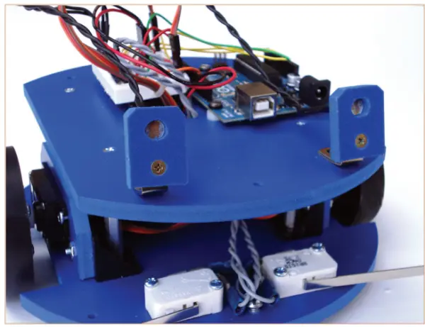
Figure 9 shows my ArdBot with the two photocell “eyes” attached to the front. I’ve bent the brackets back a bit so that the cells point slightly upward.
Refer to Listing 4 for lightsteer.pde. It uses the current values of the photocells to make quick
steering adjustments to the left or to the right. In the declarations area, the code:
const int ambient = 600;
const int threshold = 800;

/*
ArdBot steering by light demo
Requires Arduino IDE version 0017
or later (0019 or later preferred)
*/
#include <Servo.h>
// CdS cell reference values
// (you need to experiment)
const int ambient = 600;
const int threshold = 800;
int lightLeft = 0;
int lightRight = 0;
Servo servoLeft;
Servo servoRight;
void setup() {
servoLeft.attach(10);
servoRight.attach(9);
}
void loop() {
// Read light sensors connected to
// analog pins A0 and A1
lightLeft = analogRead(A1);
lightRight = analogRead(A0);
// Stop robot if below ambient
if (lightRight < ambient || lightLeft < ambient) {
stopRobot();
} else {
forward();
// Steer to right if right CdS below threshold
if (lightRight < threshold) {
turnLeft();
delay (250);
}
// Steer to left if left CdS below threshold
forward();
if (lightLeft < threshold) {
turnRight();
delay (250);
}
}
}
// Motion routines
void forward() {
servoLeft.write(180);
servoRight.write(0);
}
void reverse() {
servoLeft.write(0);
servoRight.write(180);
}
void turnRight() {
servoLeft.write(180);
servoRight.write(180);
}
void turnLeft() {
servoLeft.write(0);
servoRight.write(0);
}
void stopRobot() {
servoLeft.write(90);
servoRight.write(90);
establishes two reference values that find application in other parts of the sketch. Depending on the ambient conditions and the attributes of the photocells, you will need to conduct some trial and error with these values. Although these values proved effective in my case, you can commence with them as a baseline, but be prepared to explore alternative values as you refine the steering performance through experimentation.
The ambient value establishes the upper threshold for the natural ambient light within the room. This represents the quantity of light that the photocells encounter under standard illumination circumstances. In my case, the ambient light value hovered around 520 to 530, thus I opted for a slightly elevated value of 600 to provide additional margin.
The threshold value establishes the minimal level of light emitted by the flashlight. I configured this value to be 800, taking into consideration the utilization of a nine-LED flashlight at a distance of 1-2 feet from the robot, with new batteries. For optimal outcomes, employ a high-intensity flashlight in close proximity to the robot. Keep in mind that as you move farther away, the amount of light reaching the photocells diminishes.
- How are leaf switches wired to the Arduino for bump detection?
Connect the common and normally open terminals of each leaf switch to digital pins D2 and D3, use a 10 kΩ pull-down resistor to keep the pin LOW when unpressed, and read the pin state with digitalRead. - Can the ArdBot use interrupts for bumper switches?
Yes; attachInterrupt(0, hitLeft, RISING) and attachInterrupt(1, hitRight, RISING) monitor pins D2 and D3 so handlers set flags when switches rise to HIGH. - Does the example bumper sketch debounce switches?
No; bumper.pde and interrupt.pde do not explicitly debounce switches; they rely on inherent delays and servo timing to mitigate bounce. - What should I do if I need to use more than two switches?
Use polling for additional switches, or employ a PISO shift register like 74HC165 or CD4021 to read multiple switches while reducing Arduino I/O usage. - How are photocells connected to the Arduino?
Form a voltage divider by placing the photocell in series with a fixed resistor (example 10 kΩ) and connect the junction to an analog input (A0 or A1) to read 0–1023 values. - How does the light-steering demo decide when to move or stop?
It compares analog readings to ambient and threshold constants; if either photocell is below ambient the robot stops, otherwise it moves and steers based on threshold comparisons. - What resistor value did the author choose for the photocell divider?
The author used a 10 kΩ series resistor based on measured photocell resistances around 10 kΩ in room lighting. - How can I increase switch contact area for bump detection?
Attach larger pieces of plastic, metal, or music wire to the leaf switch contact by soldering or adhesive, being careful not to add so much weight that it causes false triggers. - What are suggested ambient and threshold values for the photocell sketch?
The article used ambient = 600 and threshold = 800 as starting points, but advises experimenting for your lighting and photocells.