Okay so the Title is indeed a bit of a mouthful lol !
Ive been needing to mess around with a desire for MORE Input/Output pins than the Arduino UNO and nowadays the UNO uses an Atmega328 microcontroller, & its limited to only about 20 Input/Output pins 🙁
Well if you’ve been messing around with Breadboard Arduino-UNO setups using the Atmega328 microcontrollers but you need MORE GPIO’s (General Purpose Input/Output) Pins without spending alotta cash on an Arduino MEGA, well, then this is also just for you !
Also everytime i find any “Official Instructions for Anything Arduino” there are either NO pictures or theres only one picture of each step but if theres anyone who’s only just learning then its not so obvious what things are connected to on a breadboard setup photo so i have made this Guide to show extremely clear and detailed photo’s of how this setup is connected up on a breadboard !
This is a comparison guide of a microcontroller in-between the Arduino UNO and MEGA, most of you folks may have heard of the Sanguino right?!? Well this Arduino-Compatible Variant uses the Atmega1284P-PU microcontroller (The Sanguino predecessor of this was the Atmega644 !) and this MIGHTY microcontroller packs a GREAT feature list when compared to the humble Arduino UNO’s Atmega328 microcontroller:
Okay so this is a real-quick setup of a Mighty1284 Arduino-Compatible Kit, aimed at Intermediate to Advanced Arduino Users who need a bit more from Breadboard’ing/Protoboard’ing with regards to MORE I/O Pins !
My 1st Arduino Breadboard Guide deals with How to make the Basic Arduino UNO & has all the training and background steps including alternative component choices so this Guide is only going to concentrate on getting the Arduino IDE Software modified Quickly, Easily and to get this Kit Setup on a Prototype Board (aka Breadboard, lol !) and in only a few short but sweet steps !
This is also assuming that you’ve sourced all the parts needed, and this is more for my reference and so when i do forget how to get this all done and setup, it will always be here for all (including myself, lol x 2 !) to see and explore !
All these components are commonly available through ebay, my favorite electronics superstore, lol, but sometimes it is cheaper to actually go to an actual electronics supplier either online or local town (if your town is lucky to have an electronics store that sells microcontrollers !)
Okay so for this Breadboard Kit, you get the following in a bare-bones package essential to get it up and running but with reverse polarity protection & status LED’s: (The Numbers in brackets indicates Quantity)
Ingredients:
(1) ATMEGA Chip: ATMEGA1284P-PU – Supplied with the “Mighty1284 Bootloader” Pre-Loaded
(2) 0.1uF Ceramic Capacitors
(2) 47uF Electrolytic Capacitors
(2) 22pF Ceramic Capacitors
(1) 16 Mhz Quartz Crystal (or 20 Mhz !)
(2) 1k Resistors, 1% Tolerance or 5% Tolerance
(2) 10k Resistors, 1% Tolerance or 5% Tolerance
(1) 1N4004 Voltage Protection Diode
(1) 3mm LED 1 BLUE (For Loading Blink Sketch)
(1) 3mm LED 2 GREEN (Power-On LED)
(1) Tactile Push Switch (6mm x 3mm)
(1) 5v Voltage Regulator (for the sake of this Guide i am using a 300mA {0.3A} Regulator !)
Which is GREAT For Low-Power Battery Operated Projects!
NOTE:
DO NOT USE The Voltage Regulator if You Are Powering this Breadboard Setup Via The USB Adapter – Instead join the 5v and GND wires from the USB Adapter to the POWER RAILS of the breadboard – Sorted !
Essentials (Do Not Proceed without this Stuff !):
*** Anti-Static Wrist Strap & Grounding Cord *** IF you DONT have an Anti-Static Wrist Strap, you Risk your Microcontroller Being Damaged Beyond any Kind of Repair Through Static Discharge from you – Best be safe than sorry here… !
*** Something To “Ground Yourself-To” Using the Grounding-Cord ! ***
Single Core Wire, 0.6/0.8mm
Breadboard
USB TTL to Serial Converter Adapter ( I will use a cheap but modified PL2303 Module, Modified to Upload Sketches Automatically ! )
Power Source ( Either from 9 to 12v if using Mains/Battery-Pack with use of the Voltage Regulator OR Supplying Power through the USB Module ! )
*** DO NOT TOUCH BARE MICROCONTROLLERS WITHOUT WEARING AN ANTI-STATIC WRIST-STRAP & GROUNDING-CORD ACTUALLY “GROUNDED” – I AM NOT RESPONSIBLE FOR ANY DAMAGE CAUSED TO ANY MICROCONTROLLER/S FOR YOU FAILING TO OBSERVE SPECIAL ATTENTION TO ESD SENSITIVE DEVICES ***
Tools:
Tweezers
Small Needle-Nose Pliers
Wire Strippers OR Stanley/Xacto Knife
Voltmeter or DMM (Digital MultiMeter)
NOTE:
These tools are not all essential but are extremely handy for fault-finding where possible problems are, should anyone encounter any, & at all times, Double-Check, Tripple-Check — Then CHECK AGAIN BEFORE APPLYING POWER to anything setup on a breadboard and at this point…..
WARNING & DISCLAIMER:
I am NOT Responsible for any Negligence or failure to follow simple health & safety procedures of any tools or Safeguarding Against Any ESD Electronics Sensitive Components that would cause you to unknowingly or accidentally damaging either yourselves or your components & to make sure you know EXACTLY what you are doing when prototyping with electricity, sharp objects & any tools you possess, Please do so with a good measure of common sense – If under-age, make sure an Adult is Supervising you at all times.
Now with all that out the way, lets begin constructing this on the breadboard !
I am using an 830 Tie Point Breadboard but will only use up half of the space so that the rest can be used for your prototyping area to have fun with this exciting microcontroller!
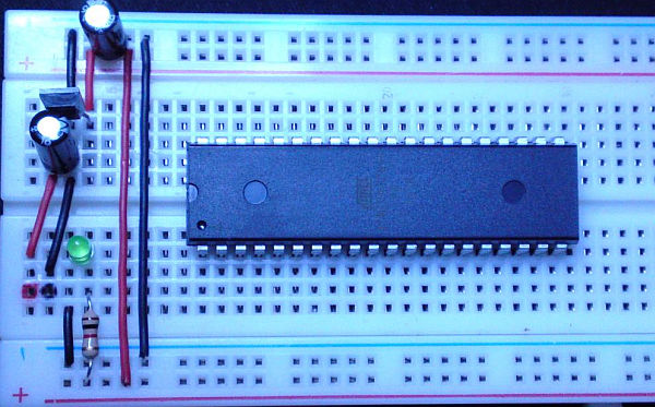
Okay so we will start off with the Power Supply Section, remembering that the way im doing this is to Ultimately save space on your Breadboard but if your well-seasoned with building breadboard circuits, please do as you require !
1st of all, Try to Keep the BLACK & RED Power wires as the same colours as in this Guide because this just makes it easier to see very clearly & quickly if a wrong connection has been made so that it will further aid you in troubleshooting later, in case something was inserted incorrectly, but this breadboard setup has been thoroughly tested and has been tripple to quadruple-checked and then checked once more because overkill is so under-rated & for peace of my mind lol !
Look at the pics below, left and right, start by inserting the RED & BLACK power lines exactly as shown:
Also See that ive marked the breadboard holes with my sharpie pens – Where the INPUT VOLTAGE wires will need to get inserted into – so whether you are using a battery pack or mains DC Voltage, this is where it would need to enter, use only the RECOMMENDED 9v to 12v of input voltage as this will NEVER put a strain on the voltage regulator !
For more detail: How To Make The Easiest Breadboard Arduino-Compatible Sanguino-Equivalent