Summary of How to Make a Basic Ultrasensor Keyboard Prototype With Arduino
This article guides readers through building a primitive musical soundboard using an Arduino and an ultrasonic sensor as a keyboard. The project involves mounting components on a wooden board, wiring the HC-SR04 sensor and a passive buzzer, and uploading custom code to trigger notes based on distance. A bonus section explains how to integrate an RGB LED for visual feedback, detailing both hardware connections and software adjustments.
Parts used in the Ultrasensor Keyboard Prototype:
- Wooden board (approx. 27cm x 32cm)
- One passive buzzer
- One ultrasonic (HC-SR04) sensor module
- 1-2 breadboards
- Approximately 5-10 woodscrews
- Approximately 2-3 male-to-male wires
- 4 female-to-male or Dupont wires
- One Arduino
- 6-12 woodscrews
- Ruler
- Pencil and/or pen
- Screwdriver
- 1 RGB LED
- 4 more male-to-male wires
- 3 220 Ω resistors
For this Instructable, I have made a primitive musical soundboard using an ultra sensor as a keyboard. Here I will show you the basic steps on how to create such a device yourself. Later on, in December, I will demonstrate to you how to make a more complex or soldered version of this soundboard with the Arduino.

Supplies

What You Need (some examples of the materials are demonstrated above):
- Wooden board to make the keyboard sturdy, approximately 27cm x 32cm is wide enough.
- One passive buzzer
- One ultrasonic (HC-SR04) sensor module
- 1-2 breadboards
- Approximately 5-10 woodscrews
- Approximately 2-3 male-to-male wires
- 4 female-to-male or Dupont wires
- One Arduino
- 6-12 woodscrews
Other Basic Materials
- ruler (preferably one that measures in cm or mm)
- pencil and/or pen
- tape
- screwdriver
BONUS:
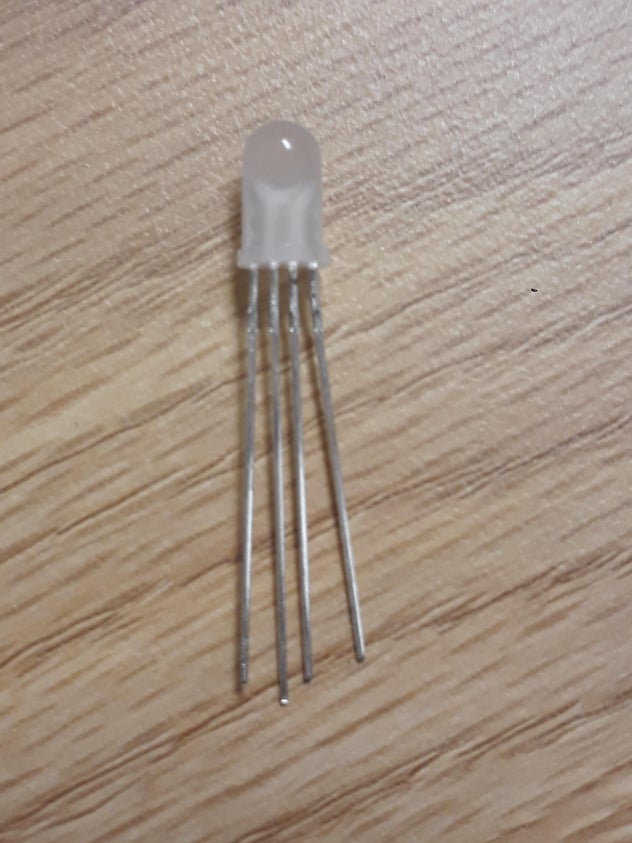
- 1 RGB led
- 4 more male-to-male wires
- Possibly 3 220 Ω resistors.
Code requirements:
- Arduino Libraries “pitches,” “SR04.h”
- Buzzer Code
MOST IMPORTANT REQUIREMENTS:
- Patience
- Self-confidence
- Self-love
- tenacity
Step 1: Setting Up the Board
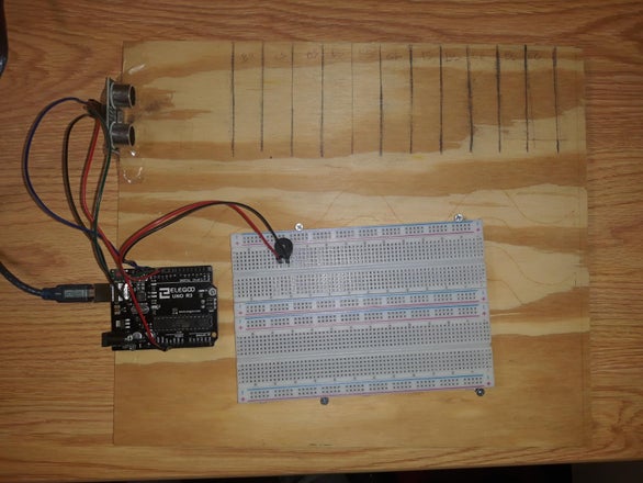
The first thing you would want to do is set down your wooden board. Then place your Arduino, Ultrasensor, and breadboard in a way that they are accessible and close to one another, yet spacious enough for the Keyboard. As you can see with my finished prototype, I originally intended to have more components in my project, which is why mine is so spacious, but due to time constraints and issues with the button switches, I had to remove those components. Oh well, it’s just a prototype in this stage; less is more, I suppose. Will probably add them later on in December.
Anyway, I recommend you arrange your board like this, as you can see above in the diagram.
Step 2: Drawing the Notes
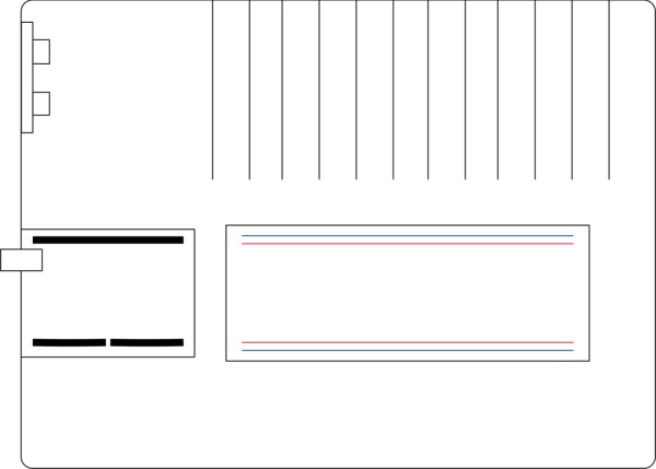
The next step of this process would be to measure the sides of your wooden board. The first thing to do is make a mark 6-8 cm away from the ultra sensor. The next thing to do is after you make after your first mark is make an additional 2 cm marks all the way to the end as seen in the diagram above. Say, if you plan to have eleven notes, draw twelve lines. If you plan more, do more, but make sure they’re at least 2 cm apart, otherwise you would have to reprogram your prototype later on.
Important note:
It would also probably help if you mark some distance that is even numbered so it would be easier to program later on.
Step 3: Securing the Board
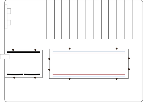
After you place your components in a way you prefer, mark over them with a pencil or pen. Then use the woodscrews and screw them into the holes on the side of the Arduino (if you don’t get it yet, those little protruding holes on the side of your Arduino are for woodscrews) and the soundboard. Since this is a prototype and it doesn’t need to be too fancy, you can use tape, another wooden block, or even glue if you so choose to secure the ultra sensor. For my prototype, I used tape. Just make sure that the ultra sensor has a clear area and is not blocked by the tape, a woodscrew, etc. You can refer to the diagram with the black dots, each black dot signifies a woodscrew, which gives you a general idea of where to place your screws.
If you want to, you can even take off the adhesive strip and attach the breadboard to the wood, but I wouldn’t recommend that if you plan to use that breadboard again.
Important note:
When it comes the wood you have and the material,the minimum number of screws needed to secure your Arduino would be two, the minimum number of woodscrews for the breadboard would be four. You can add more if you wish, but its already secure as is. That is the number I went with for my prototype.
Step 4: Wiring the Ultrasensor
Now, this is the fun part. The first thing you want to do is wire your ultra sensor to the Arduino. Now, its time to get your female-to-male wires. With these pins, connect one to The Echo slot so the pin goes into pin 11, and the trigger pin goes into pin 12. The Vcc pin, or the power pin, goes into the 5v analog pin, and obviously, the ground goes into the ground pin. For this project, but the ground pin is in the analog section.
Important note:
Also, know that the trigger part of the ultra sensor analyzes the distance of an object away from the sensor; the echo pin emits a low-frequency ultrasound 40,000 Hz or 40 kHz (Understanding How Ultrasonic Sensors Work, Rodrick) to detect distance. You can think of the ultra sensor in the same way as a bat using echolocation to find food. So make sure the components are connected to the pins before you begin coding.
Step 5: Wiring the Piezo
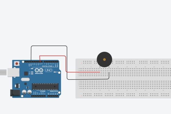
The next thing we want to do here is adding the Piezo buzzer; if you look at a piezo buzzer, you’ll notice it is polar, like an led. On the bottom, you can see that one side is negative while the other is positive. If you get confused while wiring, as I did, you can always look at the top, and there will be a positive sign near the positive leg. I have taken two pictures with a piezo so you can get a good picture of where everything is. Get a male-to-male wire and connect the negative to the ground pin on the arduino and the positive leg to pin 9.
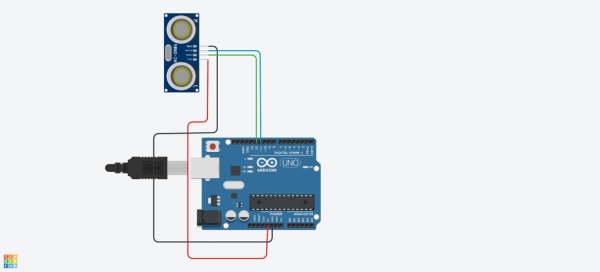
Step 6: Putting Them Together
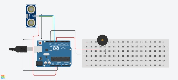
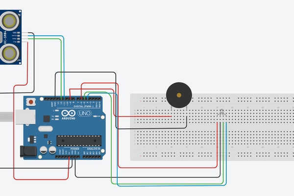
Now that you have wired both components, it should look like something roughly similar to this. What will happen here is when the code activates the ultrasensor will find a distance with a set range, once in this range, the data will be sent to the buzzer which will emit a tone based on the range from the ultrasensor. It should look similar to the diagram above. The wires have been moved for clarity.
Step 7: The Code
Make sure you download the code below you so the final prototype works properly.
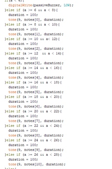
So now that we have the code components let us look at it very carefully. You’ll notice that the pins for the passive buzzer and the ultrasensor are already defined.
You’ll will also notice that there is an array with a vast amount of notes. I have already a prearranged notes that i selected for my prototype, however, you can adjust this notes by changing the notes and refering to the pitches library. You can also adjust note duration and delay in the if statement below. Or you can do a mix of both, go wild.
Important note:
If you haven’t already downloaded this library, or the SR04 library for that matter, do it now.
If you plan to create a longer keyboard with moe notes, feel free to add them now. However, make sure to write down the names of each key on each spot where you wish that note to play so it will be a bit easier when testing it out. I used a pencil for mine, but if that is too light for you than use a pen.
Step 8: Quick Side Note: Downloading Arduino Libraries
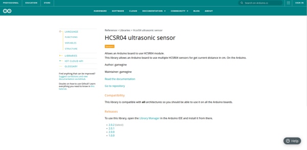
If you are having issues downloading the libraries, what you will need to do is save the library as a zip, and then extract that zip folder to your Arduino Library. Alternatively, you can just use the library manager that is already in the Arduino. If the library you are looking for is not there then just download it as a zip and extract to your library folder. Please make sure that the name of the library is the same as the library folder or the computer won’t recognize it. For more information on how to download and install a library you can refer to this page as an example.
https://www.arduino.cc/reference/en/libraries/hcsr04-ultrasonic-sensor/
Step 9: Uploading the Code
Now that you have all the adjustments you need. Feel free to run it, but make sure to test it out before you seriously play with it. If it plays a not from the specific distance you desire, than congratulations! You made your prototype Ultrasensor keyboard!
Step 10: BONUS
**insert other pictures here.
Now that you have read through my ramblings, you desrve a treat! This treat is in the form a RGB led. For the regular prototype, we used a ultrasensor as an input, and a speaker as an output. This bonus takes it one step further and adds a second output, a RGB led!
Step 11: Wiring the RGB LED
Adding an rgb to your project is not that different from last time. In-fact, its layout is similar to the ultrasensor, we just need four spots to place a wire and connect it to our arduino. Now, the longest leg on the rgb is the cathode, that goes into ground. The one to the left is the Red RGB input, which goes into the six pin, and the two on the right are the green RGB and the blue RGB, those go into five and four respectively. Your RGB led should work like this. For my Arduino, the RGB seems to workj fine without resistor because of the low power it is emitting; however, I do reccomend you use three 220 Ω ohm resistors for each rgb just in case.
Step 12: Coding the RGB LED
*insert video here.
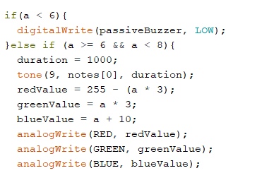
Here is the finished product for this bonus. Here, you can tell I added extra stuff to the if-statement, light data is used from the input data from the ultrasensor. Its good to use as a sort of back-up for the speaker incase something happens to it, then you will know tht there is an issue with the speaker and not the ultrasensor. It is also good for a prototype before working on something like a Neo-pixel. Say, if you want to see what something will do before its encoded into a Neo-pixel strip, RGB leds, in my opnion, are the best go to. If not, then I apologize. Fair warning, I don’t really mind the way the rgb outputs ight in this current, but there is a slight chance it will flash due to the data from the ultrasensor. So if your sensitive to flashing lights or have epilepsy I would suggest a long delay on the light. Or if you feel too unsure with testing out the light then I reccomended ignoring this section entirely.
Step 13: Uploading and Running
Here is what it should look like with all its components.
Step 14: Code Sources and Inspirations
Here are links to the code referenced, I will also add the code I used to create my code, most are open source but I will still cite them anyway.
Bibliography:
Arduino (2010) Pitches.h library (version 1.0) [source code] https://www.arduino.cc/
Arduino (2016) SR04.h libary (version 2.0.1) [source code] https://www.arduino.cc/
Burnett, Roderick. “Understanding How Ultrasonic Sensors Work.” Understanding How Ultrasonic Sensors Work Comments, Publisher Name MaxBotix Inc.Publisher Logo, 4 Mar. 2021, https://www.maxbotix.com/articles/how-ultrasonic-sensors-work.htm.
codebender_cc. “How to Use an RGB Led – Arduino Tutorial.” Instructables, Instructables, 7 Oct. 2017, https://www.instructables.com/How-to-use-an-RGB-LED-Arduino-Tutorial/
Elegoo (2016) SR04 example source code (version 2.0.1) [source code] https://www.elegoo.com/
Elegoo (2016) RGB_LED source code (version 1.0) [source code] https://www.elegoo.com/
Igoe T (2010) Passive_buzzer source code (version 1.0) [source code] https://www.arduino.cc/
Jabbaar, Arbi Abdul. “Ultrasonic Sensor HC-SR04 with Arduino Tutorial.” Arduino Project Hub, Arduino, 17 Sept. 2019, https://create.arduino.cc/projecthub/abdularbi17/ultrasonic-sensor-hc-sr04-with-arduino-tutorial-327ff6.
The Arduino Team. “HCSR04 Ultrasonic Sensor.” HCSR04 Ultrasonic Sensor – Arduino Reference, Arduino , https://www.arduino.cc/reference/en/libraries/hcsr04-ultrasonic-sensor/
The Arduino Team. “Play a Melody Using the Tone() Function.” Arduino, Arduino, https://www.arduino.cc/en/Tutorial/BuiltInExamples/toneMelody.
Inspirations:
Published by Device Plus Editorial Team, “How to Make Arduino Speakers – in Depth Speaker Tutorial.” Device Plus, MaxBotix, 4 Sept. 2020, https://www.deviceplus.com/arduino/entry019/.
Source: How to Make a Basic Ultrasensor Keyboard Prototype With Arduino
- How do I connect the ultrasonic sensor pins?
Connect the Echo pin to Arduino pin 11, the Trigger pin to pin 12, the Vcc pin to the 5V analog pin, and the ground pin to the ground pin. - Can I use tape to secure the ultrasonic sensor?
Yes, you can use tape, another wooden block, or glue to secure the sensor, provided it does not block the clear area of the sensor. - What is the minimum number of screws needed for the Arduino?
The minimum number of screws needed to secure the Arduino is two. - How should I wire the positive leg of the piezo buzzer?
Connect the negative leg to the ground pin on the Arduino and the positive leg to pin 9. - Does the ultrasonic sensor emit high-frequency sound?
Yes, the echo pin emits a low-frequency ultrasound at 40,000 Hz or 40 kHz to detect distance. - What libraries are required for this project?
You need the Arduino Libraries "pitches" and "SR04.h". - Where should I place the marks for the notes on the board?
Make a mark 6-8 cm away from the ultra sensor and then make additional 2 cm marks all the way to the end. - How do I install the SR04 library if it is not in the manager?
Save the library as a zip file, extract it, and place the folder into your Arduino Library folder. - Is it necessary to use resistors with the RGB LED?
It is recommended to use three 220 Ω resistors for each RGB leg, though they may work without them due to low power emission. - What happens when the code activates the ultrasonic sensor?
When the sensor finds a distance within a set range, data is sent to the buzzer which emits a tone based on that range.