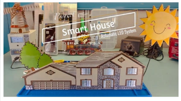
Summary of How to Build a Smart House Model
Smart House project uses the ARD-02 Arduino Basics Starter Kit to build an autonomous LED lighting and basic security system for a model house, leveraging the kit’s light sensor, LEDs, speaker, Piezo knock sensor, servos, and stepper motors. The guide adapts OSEPP example code for automatic lighting based on photocell readings, shows assembly and placement of LEDs and sensors, and outlines next steps for motion control and app-based control. Sound sensing and knock detection are built from kit lessons and integrated into the model for simple security features.
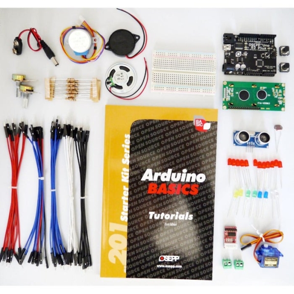
Parts used in the Smart House project:
- ARD-02 Arduino Basic Kit (OSEPP 201 kit)
- Arduino Uno (included in kit)
- Photocell / photoresistor (light sensor)
- 10K Ohm resistor
- LEDs (for first and second floor lighting)
- Speaker
- Piezo element (knock sensor)
- Servo motors (from kit)
- Stepper motors (from kit)
- Wires and connectors
- Solder and heat shrink tube (T3)
- Cardboard or LEGO building template (house model)
- White paper for windows (diffuser)
- Digital multimeter
Smart House will be the next smartphone. The technology that encompasses a smart house will become the new normal for modern-day homeowners. Smart houses range from basic to advanced depending on the sensors that are installed in the house and the operating system.
The ARD-02, 201 Arduino Basics Starter Kit, comes with everything to build a Smart House Model. The kit comes equipped with a temperature sensor for temperature control, LED lights for the house lighting system, sound for the security system, servo motors, and stepper motors for a wide range of motion control.
We want to take advantage of the lessons that come with the ARD-02 Kit, we will use their provided code and do a little modification to work with the smart house project, I will attach the link for the ARD-02 example code below for reference.
I collaborate with Circuit Specialists on this project because this project is about STEM and the company is all about STEM. Circuit Specialists and I go way back when we collaborate on the Arizona University EE robotic club robot arm project https://www.instructables.com/Circuits-Specialists…
Supplies
Step 1: Pick the House
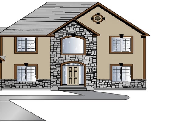
In today’s project, we will implement the “Sensing Light” lesson on page 23, which is the most basic step of a smart house, a smart LED light system. The light sensor will provide constant input from the environment and change the light level accordingly.
The light system can be set to a specific mood such as dinner, movie, party, etc. You can print the house template and glue it on cardboard with school glue, and then cut it out.
This project also works with LEGO City Series and you would have to run the wire internally within the building.
Step 2: Installing the LED System
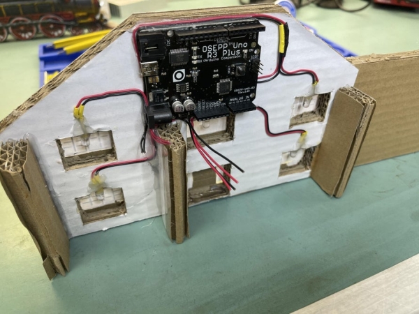
- Now you need to cut the slot for the door and windows.
- Install the LED lights for the first and second floors.
- For reference, we used glue and a white piece of paper to close up the windows for better light distribution. I will include a schematic below for the wiring.
Step 3: Assemble and Testing the Light Sensor
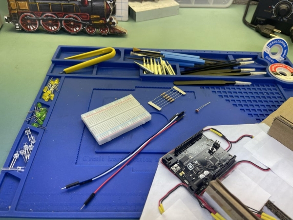
- I would test the resistor value to make sure that you have the correct 10K Ohm.
- Assembling the Light Sensor circuit to make sure everything works. I will include the schematic below for reference.
- Upload the code to make sure the Light Sensor works as expected. I will attach a link below where you can download the example file. http://osepp.com/files/osepp_201K.zip
Now, we need to make the sensor portable so that it works with our Smart House project.
- Solder the one side of the resistor to the photoresistor as in the photo below, then solder the wire according to the code.
- The Light Sensor should look like the picture below.
- Pick a location toward the roof of the house for the best light input and connect the wire to the Arduino just like the previous step.
- Now we will change the code so that in a certain light condition, the LED light system for our smart house will turn on or off accordingly.
//Project: Smart House with Light Sensor system

int First_Floor_LED = 3;
int Second_Floor_LED = 4;


const int sensorMin = 0;
// sensor maximum, discovered through experiment
const int sensorMax = 800;

// the photocell voltage divider pin
int photocellPin = A0;

void setup()
{
    // set up serial at 9600 baud
    Serial.begin(9600);
    pinMode(First_Floor_LED, OUTPUT);
    pinMode(Second_Floor_LED, OUTPUT);
}

void loop()
{
    int analogValue;
    int range;

// read our photocell
analogValue = analogRead(photocellPin);
// map the sensor range to a range of four options
range = map(analogValue, sensorMin, sensorMax, 0, 3);

// do something different depending on the
// range value
switch (range)
{
    // Dark turn on the light
    case 0:
        Serial.println("dark");
        digitalWrite(First_Floor_LED, HIGH);
        digitalWrite(Second_Floor_LED, HIGH);
        break;
    // Dim turn on the light
    case 1:
        Serial.println("dim");
        digitalWrite(First_Floor_LED, HIGH);
        digitalWrite(Second_Floor_LED, HIGH);
        break;
    // Medium turn off the ligh
    case 2:
        Serial.println("medium");
        digitalWrite(First_Floor_LED, LOW);
        digitalWrite(Second_Floor_LED, LOW);
        break;
    // Bright Turn off the ligh
    case 3:
        Serial.println("bright");
        digitalWrite(First_Floor_LED, LOW);
        digitalWrite(Second_Floor_LED, LOW);
        break;
}

// wait 0.25s before reading the photocell again
delay(250);
}
Below would be the demonstration of this add on feature for the Smart House
Step 4: What Next?
The Autonomous LED Light system is just the beginning of the Smart House project. There will also be motion control, security systems, and much more in future projects. That is not to overlook the importance of an intelligent LED light system in a Smart House.
The house of the future will always make the occupants feel welcome after a long day of work, or changing the mood of the house for a welcome home party. Furthermore, the ability to turn the light on and off from an app could add another layer to the security overall.
Step 5: How to Build a Security System
A smart house should provide its occupants with more than just comfort. It should also provide a sense of security and a smart house is no different. For the sake of argument, a smart house should do more than just provide a passive defense system for stopping intruders. A smart house should be equipped with a sensor system that actively listens to outside noise.
We will use a speaker and a Piezo element as a sound sensor. If you are following along with the ARD-02 201 Arduino Basics Starter Kit, this will be covered under these 2 lessons: Melody (pg.53) and Knock Sensor(pg.63). I will be referencing the information from these 2 lessons as they provide a great deal of information such as schematics, circuit and coding theory, explanation, etc.
Step 6: Sound Circuit
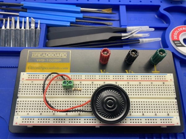
- The sound circuit is fairly simple to assemble, the resistor connects to the speaker in series.
- Plug the circuit into an Uno to make sure everything works. OSEPP provided the sound example code in this link http://osepp.com/files/osepp_201K.zip
- Now, we will try to build the same circuit with a slightly bigger speaker for our house.
- Finally, you can protect the resistor by covering it with a T3 heat shrink tube and then set it aside.
Step 7: Knock Sensor Circuit
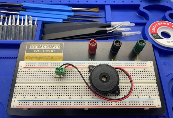
- This circuit is also fairly simple to build and test out before installing in the house.
- I usually upload the provided code from OSEPP to make sure the system works before moving on to the next step.
- Now we need to build the sound sensor so that it can go into the smart house project. The resistor is connected parallel to the Piezo Buzzer.
- Fold the wires down so the heat shrink tube can go over it. The final product should look like the photo below.
- Next, install the Sound system and the Knock Sensor to the house. Give yourself a pat on the back because the hard part is done. I will attach the schematic below for your reference or page 55 on the OSEPP handbook.
Source: How to Build a Smart House Model
- What lesson from the ARD-02 kit is used for the light system?
The Sensing Light lesson on page 23 is implemented for the smart LED light system. - How is the light sensor connected for portability in the house?
Solder one side of the resistor to the photoresistor, solder wires according to the code, and place the sensor toward the roof for best input. - What resistor value should be tested for the light sensor?
Test a 10K Ohm resistor to ensure correct operation. - How does the code decide when to turn LEDs on or off?
The code reads the photocell, maps the analog value to a range 0–3, and uses a switch to turn LEDs on for dark/dim and off for medium/bright. - Which example code is referenced for the ARD-02 kit?
The example files are referenced from the OSEPP package at http://osepp.com/files/osepp_201K.zip. - What kit lessons cover sound and knock sensing?
Melody (page 53) and Knock Sensor (page 63) lessons cover the speaker and Piezo knock sensor. - How is the sound circuit assembled?
The resistor connects in series with the speaker; test the circuit on an Uno and protect the resistor with heat shrink. - How is the knock sensor wired for the house?
The resistor is connected in parallel to the Piezo buzzer, wires folded down and enclosed in heat shrink before installation. - Can the project work with LEGO buildings?
Yes, the project can work with LEGO City Series if wires are run internally within the building.