Summary of How Rotary Encoder Works With Arduino!
This tutorial explains the working principles of incremental rotary encoders and demonstrates their integration with Arduino. It details the device's construction, signal generation (90-degree phase shift), and two practical programming examples: a position counter and LED brightness control. The guide covers hardware setup, including pin connections and pull-up resistors, to help users implement menu navigation or input devices in projects like 3D printers.
Parts used in Rotary Encoder with Arduino:
- Incremental Rotary Encoder
- Breakout board with pull-up resistors
- Arduino
- Clock (CLK) pin connection
- Data (DT) pin connection
- Switch (SW) pin connection
- Vcc power supply
- GND ground connection
A rotary encoder is a great input device for any project such as a 3D printer’s menu. So in this tutorial, we will learn how a rotary encoder works and how to use it with Arduino.

So let’s get Started!
Step 1: Watch the Video !
If you don’t want to read all the stuff you can watch my video it will be much easier to understand.
Step 2: Overview
A rotary encoder, also called a shaft encoder, is an electro-mechanical device that converts the angular position or motion of a shaft or axle to an analog or digital output signals.
There are two main types of rotary encoder
1) Absolute – The output of an absolute encoder indicates the current shaft position, making it an angle transducer.
2) Incremental – The output of an incremental encoder provides information about the motion of the shaft, which typically is processed elsewhere into information such as position, speed, and distance.
Note: One we use in our project is Incremental type so we will focus on that.
Step 3: What Is Incremental Rotary Encoder ?
An incremental encoder will immediately report changes in position(Clockwise & Counterclockwise), which is an essential capability in some applications. However, it does not report or keeps track of absolute position. As a result, the mechanical system monitored by an incremental encoder may have to be moved to a fixed reference point to initialize the position measurement.
Step 4: Construction & Working
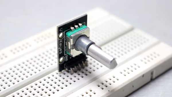
One I have comes in this breakout board which already have the required pull-up resistors on it.

It has five pins – Clock, Data, Switch, Vcc, GND
Construction:
The knob which we rotate is internally connected to the disk(Pic – 2). If we rotate clockwise or counter-clockwise it will move accordingly. The grey portion is GND and Golden contact points are connected to Vcc. There are two contact point placed at a specific distance apart which are nothing but our CLOCK and DATA line.
Working:
As we rotate our encoder, the two output will change depending upon the position of the encoder. Which will generate two trains of pulses.
If you look closely those two signals will be 90 degrees out of the phase. If the encoder rotates clockwise then CLOCK will lead and if the encoder rotates counter-clockwise then DATA will lead.
And taking a look at state change for clockwise two signals will have opposite values and for counter-clockwise same values.
And now if we programme our Arduino accordingly we can get it to work with our project.
Step 5: Programming

Example 1: (Counter.ino)
Now in this example, CLK is connected to pin 3, DT to 4 and SW to 5, then we have some variables to store data. In void setup section CLK, DT and SW are set as input and then started the serial command and here stored the current position in the last state
In void loop section first, we read the current state of the clock and using it else check it if it has changed.
If the state != last state means it has changed the position. And if data != state then CW else CCW which will increase or decrease counter accordingly.
Then using serial print printed the counter variable. And if the switch is pressed counter will reset to 0 and print it, in the end, put the state into the last state
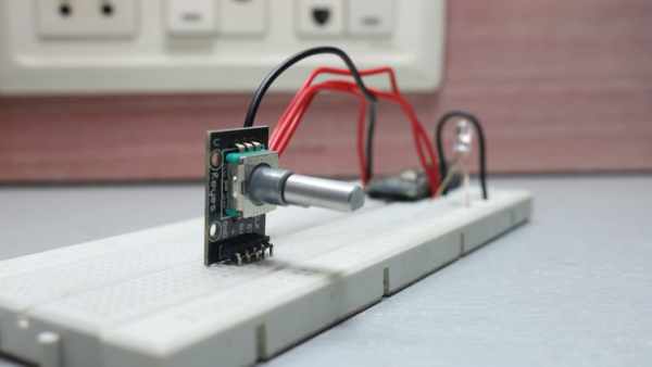
Example 2: (LEDBrightness.ino)
In this example, I have put the counter value in analog write function and used constraint function to limit the rage between 0-255 in order for it to work
Note: it’s better if you open the code in Arduino IDE and read it once
Step 6: Thank You !
Check out JLCPCB
$2 PCB Prototype (10pcs,10*10cm): https://jlcpcb.com
That’s it if you like my work
Feel free to check out my YouTube channel for more awesome stuff: https://www.youtube.com/c/Nematics_lab
You can also follow me on Facebook, Twitter etc for upcoming projects
https://www.facebook.com/NematicsLab/
https://www.instagram.com/nematic_yt/
https://twitter.com/Nematic_YT
Source: How Rotary Encoder Works With Arduino!
- What is an incremental rotary encoder?
An incremental encoder reports changes in position such as clockwise and counterclockwise motion but does not track absolute position. - How many pins does the breakout board have?
The breakout board has five pins: Clock, Data, Switch, Vcc, and GND. - How do the signals differ for clockwise rotation?
When rotating clockwise, the CLOCK signal leads the DATA signal. - Can I use this encoder for LED brightness control?
Yes, by mapping the counter value to the analog write function and constraining the range between 0 and 255. - What happens when the switch is pressed in the counter example?
Pressing the switch resets the counter variable to 0. - Do I need external pull-up resistors?
No, the specific breakout board mentioned already includes the required pull-up resistors. - Which type of encoder is focused on in this project?
The project focuses on the Incremental type of rotary encoder. - How are the signals generated during rotation?
Rotating the encoder generates two trains of pulses that are 90 degrees out of phase.