Summary of High-Power Control: Arduino + N-Channel MOSFET
Summary: This article explains how to control 12V devices (solenoids, motors, lights) from an Arduino/ESP32 using an N-Channel MOSFET (example: RFP30N06LE). It covers wiring, using a pull-down resistor on the gate, the need for a flyback diode for inductive loads, insulation/assembly tips, and optional optoisolation. STL files for a 3D-printed enclosure are provided.
Parts used in the N-Channel MOSFET Control Project:
- N-Channel MOSFET (example RFP30N06LE)
- Arduino or ESP32 microcontroller
- 12V supply (V+)
- Motor, solenoid, or light (12V device)
- Pull-down resistor (gate resistor)
- Flyback/rectifier diode (example 1N4001 or SB560)
- Heat shrink tubing
- Insulation tape
- 3D-printed enclosure (two STL parts)
- Optional optoisolator
Eventually you are going to find yourself holding a 12v solenoid, motor, or light and wondering “How the heck am I supposed to control this from my Arduino?” And we have covered this in the past. Today we are going to talk about another way of doing just that, this time with an N-Channel MOSFET metal–oxide–semiconductor field-effect transistor, specifically the RFP30N06LE MOSFET (You can pick these up from sparkfun). but you can use any N-Channel MOSFET exactly the same way.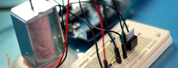
How this works
Once the code is uploaded to the ESP32, you can start building the project by using a 3D printer to create a casing for the system. The enclosure’s STL files have been shared, comprising two parts that can be assembled together.
Kindly adhere to the provided instructions in order to properly arrange all the parts for a tidy and snug placement. Using precautions such as heat shrink tubing and insulation tape is recommended to ensure proper insulation and prevent possible short circuits. WARNING: I am going to make this really simple, so pay attention… my aim is to explain in easy terms what is happening.
To begin with, a MOSFET is simply a unique type of transistor.
If you are unfamiliar with transistors, they are components with three leads that serve two basic functions: switching and amplifying (in this case, it is configured as a switch). You have an Input labelled the Source, an Output called the Drain, and a Control named the Gate. Sending a HIGH signal to the gate causes the transistor to switch, enabling current to move from the source to the drain.
Therefore, we connect our motor, solenoid, or light to the V+ terminal rather than the ground (V-) terminal. The ground is linked to the drain of the transistor. By sending a HIGH signal to the transistor’s gate, the arduino activates the transistor, allowing current to flow between the drain and source, and forming a complete circuit for the motor, solenoid, or light.
More Information
If you want to know more, or actually know what is actually going on in there. Pete over at Sparkfun put out amazing video explaining MOSFETs for a solid 20min. Highly recommended.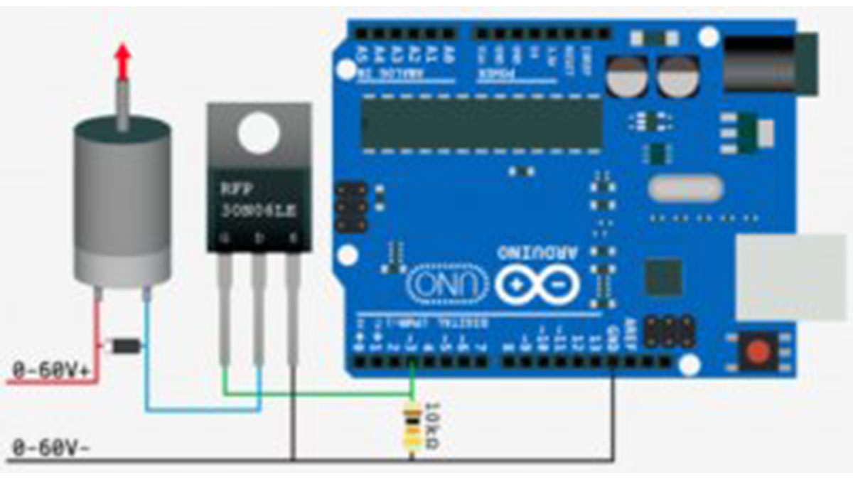
Hooking it up / What’s the diode used for?
This circuit is pretty simple. The only part that looks funny is the resistor. This is a pull-down resistor. The resistor holds the gate low when the arduino does not send a high signal. This is here incase the arduino comes loose, or the wiring is bad it will default to off. You don’t want this pin to ever be floating as it will trigger on and off.
You can see that in 2 of the 3 illustrations, there is a diode parallel to the device we are powering. Any time you are powering a device with a coil, such as a relay, solenoid, or motor, you need this guy, and don’t leave home without it. What happens is when you stop powering the coil, a reverse voltage, up to several hundred volts, spikes back. This only lasts a few microseconds, but it is enough to kill our MOSFET. So this diode (only allows current to pass one way) is normally facing the wrong direction and does nothing. But when that voltage spikes comes flowing the opposite direction, the diode allows it to flow back to the coil and not the transistor. We will need a diode fast enough to react to the kickback, and strong enough to take the load. A rectifier diode like the 1N4001 or SB560 should do the job. If you are looking for extra protection you could use an optoisolator between the Arduino and the transistor. An optoisolator optically isolates both sides (high and low power) of the circuit so the high-voltage can not possibly come back to the microcontroller.
For more detail: High-Power Control: Arduino + N-Channel MOSFET
- How do you connect a motor or solenoid using an N-Channel MOSFET?
Connect the motor or solenoid to V+, connect the device ground to the MOSFET drain, tie the MOSFET source to ground, and drive the gate from the Arduino. - Why is a pull-down resistor used on the MOSFET gate?
The pull-down resistor holds the gate low when the microcontroller is not driving it so the MOSFET defaults to off and does not float. - What is the purpose of the diode across a coil device?
The diode provides a path for reverse voltage spikes when the coil is turned off, protecting the MOSFET from kickback. - Which diode types are recommended for flyback protection?
Rectifier diodes such as the 1N4001 or SB560 are recommended in the article. - Can any N-Channel MOSFET be used the same way?
Yes, the article states you can use any N-Channel MOSFET the same way as the RFP30N06LE. - Should I insulate wiring and joints in this project?
Yes, the article recommends using heat shrink tubing and insulation tape to prevent short circuits. - Is an optoisolator necessary for this circuit?
It is optional; the article says you could use an optoisolator for extra protection to isolate the microcontroller from high-power side voltage. - What does sending a HIGH to the MOSFET gate do?
Sending a HIGH to the gate turns the MOSFET on, allowing current to flow between drain and source and powering the device.