Summary of High Heel Massage using an Arduino
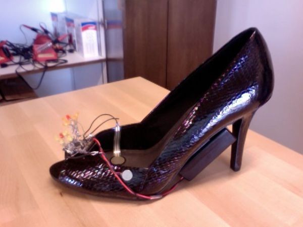
This project creates a smart high heel that detects foot fatigue using a force sensor. After sustained pressure, it activates a vibration motor for massage and illuminates an LED flower pattern on the shoe's top. Designed to offer comfort to women wearing high heels, the device adapts to individual pressure levels using an Arduino Mini Pro to control the electronics and power source.
Parts used in the Smart High Heel Massage Project:
- High heel shoe
- 14 LEDs
- Force (pressure) sensor
- Vibration motor
- Wires
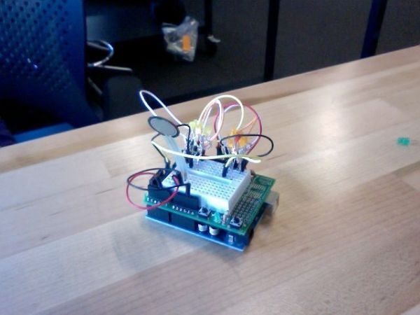
- Arduino Mini Pro 3.3V
- 9V battery pack
- FTDI TTL-232R-3V3 USB-TTL Level Serial Converter Cable
- Solder
My project is to make a heel (shoe) that senses when your foot is tired and then eases the pain. I will have a force sensor measure how much pressure is on your foot for 3 minutes. If the pressure is at a certain measure for 3 minutes, then a vibrator will go off and massage your foot for two sets of vibration massages. I am creating this because many women suffer the price of beauty and looking good. Women deserve some slack and shoes that sense when their feet hurt and provide a quick message is a perfect solution. My idea is different from other comfort shoes because the shoe adapts to the individual. The LED flower pattern that will be on the top of the shoe lights up in different patterns during the massage and gives the shoe a feminine look while embracing technology.
Materials:
high heel shoe (Payless Shoe Store)
14 LEDs (available in class)
force(pressure) sensor (available in class)
vibration motor (http://www.sparkfun.com/products/8449)
wires (available in class)
Arduino Mini Pro 3.3V (http://www.amazon.com/Arduino-Pro-Mini-328-3-3V/dp/B004G53J6M)
9V battery pack (available in class)
FTDI TTL-232R-3V3 USB – TTL Level Serial Converter Cable (available in class)
solder (available in class)
Step 1: Code for force sensor and LED
I practiced applying pressure to the force sensor and having an LED light up in response. Make sure the USB cord is connected to the Arduino even though the picture does not show it.
int sensePin = 2; // the pin the FSR is attached to
int pressureLevel = 4;
int timeCount = 0;
int pressureCount = 0;
int lengthOfTime = 5;
void setup() { Serial.begin(9600);
pinMode(2, OUTPUT); //declare the ledPin as an OUTPUT need for all pins
}
void loop() { int pressure = analogRead(sensePin) ;
if (millis() % 1000 == 0) { //60000 for one minute,
timeCount ++;
if (pressure > 500) {
pressureCount ++;}
if ((timeCount > lengthOfTime) && (pressureCount > pressureLevel)) { //activate when 4 out of 5 times
digitalWrite(2, HIGH);
timeCount=0;
}
Serial.println(pressure);
}
}
Step 2: Combining the LED, force sensor and vibration motor
int sensePin = 2; // the pin the FSR is attached to
int pressureLevel = 4;
int timeCount = 0;
int pressureCount = 0;
int lengthOfTime = 5;
int motorpin = 9;
void setup() { Serial.begin(9600);
pinMode(2, OUTPUT); //declare the ledPin as an OUTPUT need for all pins pinMode(motorpin, OUTPUT);
}
void loop() { int pressure = analogRead(sensePin) ;
if (millis() % 1000 == 0) { //60000 for one minute,
timeCount ++;
if (pressure > 500) {
pressureCount ++;}
if ((timeCount > lengthOfTime) && (pressureCount > pressureLevel)) { //activate when 4 out of 5 times
digitalWrite(motorpin, HIGH);
delay(500);
digitalWrite(motorpin, LOW);
delay(500);
digitalWrite(2, HIGH);
timeCount=0;
}
Serial.println(pressure);
}
}
Step 3: Making the Flowers
I created flowers by twisting the wires together (corresponding positive with positive and negative with negative) and then soldering them. I had to test the LEDs by applying a ground wire and 5V wire to each positive and negative wire at the same time to see if each LED would light up. If it lit up, it indicated that the wiring was done correctly. It took multiple tries to get this right. I had to test the each LED individually and record which wire was positive and which was negative. My original idea was to have three flowers. Since the third one crowded the Mini Pro Arduino 3.3V that I’m using, it didn’t look like a flower pattern, but rather a clump of LEDs. I decided to exclude it.
14 LEDs
force(pressure) sensor
vibration motor
wires
Arduino Mini Pro 3.3V
For more detail: High Heel Massage using an Arduino
- How does the shoe detect when the foot is tired?
The shoe uses a force sensor to measure pressure; if the pressure remains above a certain level for three minutes, the system activates. - What happens when the pressure threshold is met?
A vibration motor turns on to provide two sets of vibration massages while the LED flower pattern lights up. - Can the shoe adapt to different individuals?
Yes, the idea differs from other comfort shoes because the shoe adapts to the individual based on their specific pressure measurements. - What is the purpose of the LED flower pattern?
The LEDs light up in different patterns during the massage to give the shoe a feminine look while embracing technology. - How many flowers were originally planned versus used?
The original idea was to have three flowers, but one was excluded because it crowded the Arduino Mini Pro. - Does the code check pressure every minute?
No, the code checks pressure every second within a five-second window to count how many times the pressure exceeds the limit. - What component controls the entire system?
The Arduino Mini Pro 3.3V acts as the central controller for the sensor, motor, and LEDs. - How are the LEDs connected in the flower design?
The wires are twisted together by matching positive with positive and negative with negative, then soldered. - What power source is used for the project?
A 9V battery pack is used to power the circuit components. - Why was the third flower removed from the final design?
The third flower crowded the Mini Pro Arduino 3.3V, making the pattern look like a clump rather than distinct flowers.