Intro
It’s quite a common problem when building electronics that some components need cooling which is usually done through some sort of heatsink and optional fans. Choosing the right cooling solution can be a difficult task because the real life behavior of the system is hard to predict or model. In my case I have faced the simple question quite a few times: how much heat can a cooling system dissipate? The thermal resistance of a particular heatsink may vary quite a lot depending on the surroundings or it can simply be unknown to start with. The aluminum side wall of an enclosure made me build this thing.
Design
This is why I have made this little device: a thermometer, a transistor and a microcontroller with a simple command line interface. I could have answered my questions in quite a lot of simpler ways, but since I made a simple thermometer not much else is needed to control the transistor when a DAC is available in the microcontroller.
The device works in a simple way: a specific power is dissipated on a transistor while a DS18s20 temperature sensor measures the temperature on the heatsink as close as possible to the transistor. The circuit uses a serial connection and is controlled via the terminal. A few preset values are available for the power to be dissipated.
The micro at the center of the project is an ATXMEGA32A4U and I am using a small board I designed for another project and another proto board which contains a current sensing resistor and a voltage divider to measure the supply. A TL431 is used as a 2.5V reference. The circuit uses two supplies, one for the micro which also contains a 3.3V LDO and one for the dissipating transistor. The schematic is shown below:
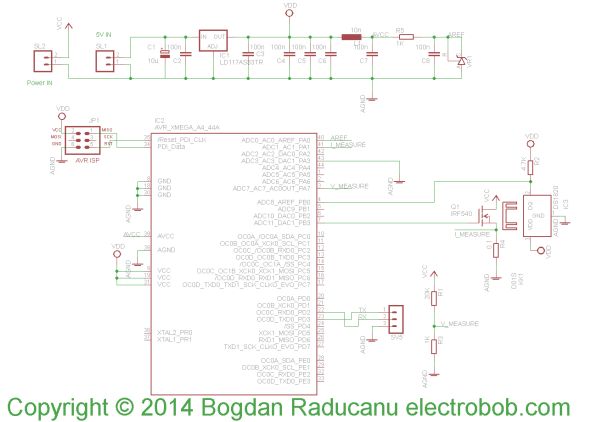 The reason for leaving the supplies separate was to be able to use a wide range of supplies for the dissipating transistor; the circuit is designed to measure up to 52V input. Such a supply is too high for a normal regulator for the micro. If the allowed maximum is lowered, a regulator can power the micro as well. In practice it turned out the low power levels (0.5 – 5W) are regulated better when a low voltage supply is used for the transistor (3V). For higher output power (5W to 50W) a 19V laptop power supply worked just fine. The limit simply comes from the ADC precision and the value of the current sensing resistor.
For more detail: Heatsink Tester