
Summary of HB-LED flashing beacon repurposes switching regulator
This project is a portable LED flasher/beacon using an MC34063 switching regulator to pulse a 1W power LED at about 5% duty cycle from a 6–12 V DC supply. It provides brighter, efficient flashes compared with incandescent flashers and uses a 1 Ω sense resistor to implement peak-current limiting by monitoring voltage drop at the regulator switch.
Parts used in the HB-LED flashing beacon:
- MC34063 switching regulator IC (8-pin DIP)
- 1W power LED
- R1 1 Ω sense resistor
- Supply battery 6V or 12V SLA lantern battery
- Circuit connections/wiring and PCB or perfboard
This flasher/beacon circuit can be employed as a distress signal on highways, a direction pointer for parking lots, hospitals, and hotels, etc. The circuit uses a power LED, and provides more light than a typical incandescent lamp flasher. Use of a 6V or 12V SLA lantern battery makes the circuit portable.
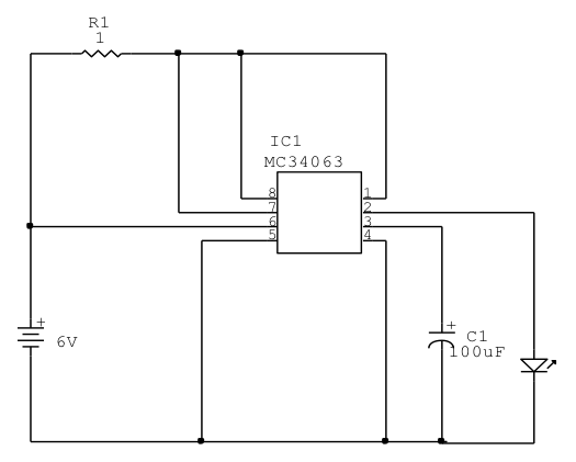
The heart of the circuit is an MC34063 monolithic switching regulator subsystem, originally intended for use in DC-DC converters. This device contains a voltage reference, comparator, controlled duty cycle oscillator with an active peak current limit circuit, driver, and a high current output switch, all in an 8-pin DIP.
The circuit briefly flashes a 1W power LED from a 6V to 12V DC supply – at about 5% duty-cycle. Current limiting to the LED is accomplished by monitoring the voltage drop across R1, a 1Ω sense resistor placed between VCC and the output switch, pin 1.
For more detail: HB-LED flashing beacon repurposes switching regulator
- What is the core IC used in the beacon?
The core IC is the MC34063 monolithic switching regulator. - What LED type does the circuit flash?
The circuit flashes a 1W power LED. - What supply voltages are supported?
It operates from a 6V to 12V DC supply, such as an SLA lantern battery. - How bright is the beacon compared to incandescent flashers?
The power LED provides more light than a typical incandescent lamp flasher. - What duty cycle does the circuit use for flashing?
The LED is flashed at about a 5% duty cycle. - How is current limiting to the LED achieved?
Current limiting is done by monitoring the voltage drop across R1, a 1 Ω sense resistor placed between VCC and the MC34063 output switch (pin 1). - Can the circuit be used portably?
Yes, using a 6V or 12V SLA lantern battery makes the circuit portable.
