Summary of Halloween Pop-Up Prop
This article details a DIY Halloween project transforming a store-bought witch prop into an automated pop-up scare. The creator mounts the prop on a pneumatic cylinder to make it burst from a hidden window well. A PIR sensor detects approaching trick-or-treaters, triggering an Arduino Nano and Particle Photon system to activate the solenoid and start the prop's animation, creating a dynamic surprise effect.
Parts used in the Halloween Pop-Up Prop:
- Halloween Witch Prop
- MAL20X600 Pneumatic Cylinder (20mm Bore, 600mm Stroke)
- Zinc-plated slotted Angle bar (1-3/8" x 18")
- Zinc-plated punched flat bar (1-3/8" x 29")
- Zinc-plated square slotted tube (1x1" x 18")
- Hex Bolts, Washers, and Nuts (1/4")
- 3-D Printed parts (witch_bracket1, witch_bracket2, halloween bracket)
- Sainsmart 8-Relay board
- Arduino Nano Every
- Solenoid Switch
- Particle Photon
- 5VDC and 12VDC Power Supplies
- HC-SR501 PIR Sensor
- 2" Black PVC pipe and 6" length cap
This was my first animated Halloween prop. I found this witch at the local hardware store. It was meant to hang up by a cord and if someone came close to it, an infrared sensor would trigger the prop. The prop has LED eyes that would light up and it would trigger a voice tract that also moved the jaw. I thought it would be cool to mount it to a pneumatic cylinder and make it pop up from hidden location, giving the kiddo’s a scare!
Off to my prop hack!
Supplies
Hardware:
- Halloween Prop (1) – See notes
- Pneumatic Cylinder, MAL20X600 (1) 20X600mm Double Acting , 20mm Bore, 600mm Stroke
- Zinc-plated slotted Angle bar (4) 1-3/8″ x 18″ Everbuilt, 1/16″ thick
- Zinc-plated punched flat bar (1) 1-3/8″ x 29″ Everbuilt, 1/16″ thick
- Zinc-plated square slotted tube (1) 1×1″ x 18″, Everbuilt, 1/16″ thick
- Hex Bolts (AR) 1/4″
- Washers (AR) 1/4″
- Nuts (AR) 1/4″
- witch_bracket1 (1) 3-D printed part
- witch_bracket2 (1) 3-D printed part
- halloween bracket (1) 3-D printed part
- 4-strand wire (AR) 5VDC, GND, Switch1, Switch2
Electronics:
- Sainsmart 8-Relay board (1)
- Arduino Nano Every (1)
- Solenoid Switch (1)
- 1/4″ pneumatic hose (AR)
- Particle Photon (1)
- 5VDC power Supply (1) 10 A (or AR) Used for all electronics and remote devices
- 12VDC power supply (1) 1A (or AR) Used for the solenoid drive
Step 1: Prop Hack!
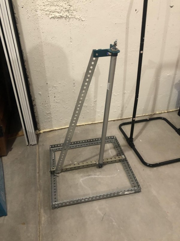
First thing is to make up the frame to hold the pneumatic cylinder. I went to the local hardware store and got some perforated angle iron so I could cut to size and bolt together.
I used some 1-1/2 in. Zinc-Plated Slotted Angle stock cut to approximately 18 inches long. I overlapped the edges and bolted together to make the base. I then had a square tube for the pneumatic mount, bolted through the center of the square base. Using a square brace would be a bit more solid and stiffer for the cylinder.
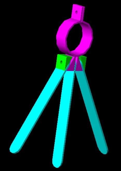
I then bolted my pneumatic piston just forward to the center of the square tube. I needed a way to stabilize the top of the piston, so I made up a 3D Printed part that bolts to the top of the piston. I made a tabs at 90 deg. One tab attached to a cross brace to hold the piston vertical. The second one was for additional support. I did find, that only one brace worked just fine. You might see how I slanted the piston a bit forward. This worked better when he prop jumped out of the window well, it actually lets the prop jump a bit forward toward the kids and leans slightly over the edge of the window well. The cylinder piston rotates freely and by having it slanted slightly allows gravity to keep the prop facing forward. Experiment with this and adjust as you go.
Step 2: Mount the Prop to the Piston Shaft
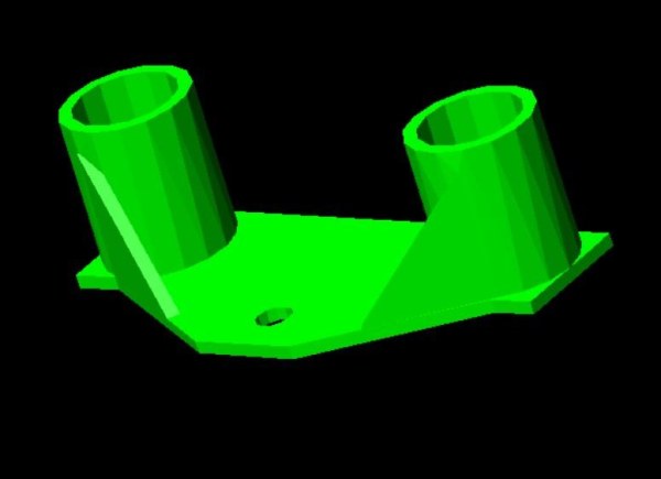
I needed a method to mount the prop to the piston. The piston has a threaded end and I found a wing nut so that I could easily disassemble the prop for storage. The Witch head had two circular tabs that extended down from the electronics box that is attached below the head. I designed up a part to fit over the tabs and a plate to go over the threaded end of the piston and tightened down with the wing nut. I went back to my trusty 3D printer and printed it up! Dang I love that thing.
Step 3: PIR Sensor
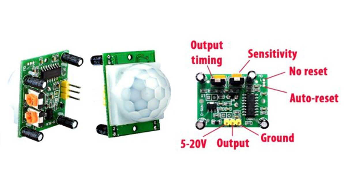
I use a simple PIR sensor (HC-SR501). This is a very cheap sensor that is widely used. Lots of on-line information on how to use this and how to use with an Arduino. The field of view is very wide. One could adjust the sensitivities but I needed something that would have a very narrow field of view so that it would only trigger when someone passes directly in path of it. You can experiment with the sensitivity so that it works as you like. The output timing is how long the output pulse lasts. I kept it pretty short, long enough for my micro controller and code loop to detect an event. It is a pretty long length of wire, but it seems to work OK.
So I came up with a sensor assembly that I can mass produce and use for all my Halloween props.
Step 4: PIR Sensor Assembly
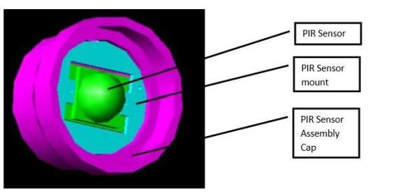
The assembled cap is placed on the end of a 6” length of 2” black PVC pipe so that the PIR has a very narrow field of view. The end of the cap also has a hole in the back for the +5VDC, GND and PIR Detect cable. I made up my own connector where one end plugs into the PIR 3-pin header and the other end is a JST-SM type 3-pin connector (no reason, I just had a few of those hanging around).
Step 5: Finished Sensor
I also 3D printed a clamp and legs so I can set the sensor in the best location. I used wing nuts to quickly adjust the legs and clamp as needed.
The sensor is positioned in such a way that when the trick or treaters approach it kicks off the animations just at the right time automatically. The PIR Sensor is connected through a long-shielded cable to the master controller, which I hide in my garage along with my air compressor.
Step 6: Schematics and the Circuits
Now that you have your personal touches added, you need a way to make it come to life!
As I mentioned previously, I have several other animated props other than this one. I won’t go over all the the others, but here is the link:
The Knight Halloween Instructable goes into much more detail on the overall master controller, how I distribute power out to each prop as well. I will focus mainly on the microcontroller and code for this prop.
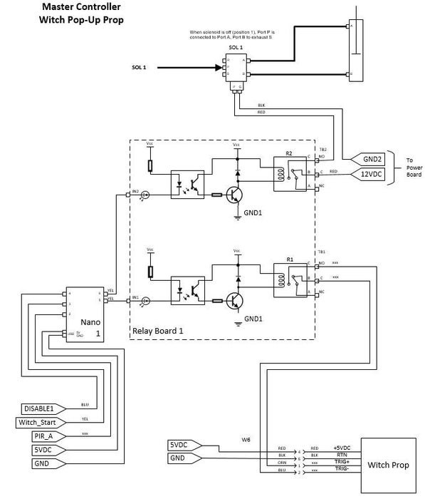
The picture here is the primary schematic for the controller for this prop. The schematics on power distribution, switches and the Particle Photon control is in the main Halloween page.
In this example, you need a smart device to run some code, like an Arduino. In this implementation I used a Arduino Nano Every. Not shown in this schematic I have a Particle Photon I use for remote control of all my props. The Particle Photon has an Arduino compatible microcontroller and also includes a Wi-Fi transceiver so you can control the whole thing anywhere using my phone, pad or PC. I also used a relay board to control the prop on/off as well as activating the pneumatic piston.
The prop out of the box has several ways to start the animation. One is a push button “Try Me” for display demos (you see that in the store displays). It also has a jack for a remote pad switch. The last is an IR sensor built into the prop that will trigger if someone comes close.
The electronics box has a switch: OFF or Try Me/Pad, On (runs all the time) and AUTO. Off is off (duh) or only starts if the switch is closed. ON cycles through the animation continuously. AUTO uses the IR sensor installed onto the prop. I removed the try-me switch and Sensor. I use the switch in the the OFF or Try Me/Pad selection. I fed that long two-wire cable I made earlier out to my controller so that I can remotely start the prop. By shorting those wires through a relay, it acts as a switch and the animation starts.
Step 7: Schematic Walk Through
Back to the schematic……
For this prop I used two relays. One to start the animation (switch) and another for the pneumatic solenoid to drive the piston.
My solenoid requires12 VDC to drive the coil which I run that through the relay board. When not driven the solenoid is in the Port A position (piston retracted). When I close the relay 12VDC drives the solenoid and it switches to port B. I must keep this activated until the animation sequence completes. My Knights Halloween page has a pneumatics overview on how all that works.
The Arduino controller has three inputs. There is an Enable input, which is connected to a switch and used to enable or disable the prop locally. Another input is Witch_Start. This is a signal from the Particle Proton. Another input is a Passive Infrared (PIR) sensor (PIR A). The PIR sensor detects when someone comes close to the prop. I have a bit more on my sensor later.
The Nano is programmed to first check if the prop is enabled (the local switch), if not it returns to the start loop and will continue looping until I enable it. If enabled, it then checks to see if it is being remotely commanded to start (Witch_Start) from the Photon. If so, it initiates the animation cycle, if not it continues and then checks to see if the PIR sensor (PIR A) detected someone. If not, it returns to the loop and continues until something happens. I’ll go through this in the code walk-through. The Nano has two outputs, one triggers a relay to enable a solenoid connected to a compressor. The solenoid is connected to the pneumatic cylinder that pops up to make the prop jump out from a window well (that I also fill with fog). The other output is a signal that is transmitted to the prop to start its animation cycle.
I have lots of schematics, might be hard to go back and forth – but don’t worry, I have the entire set later on for download, so bear with me.
Step 8: Code Walk-Through

The attached is the full code for controlling this prop using all the devices described on my main page.
As I mentioned I have a master controller, along with the pneumatic solenoids and air compressor located in my garage that controls the whole thing. I’m going to mainly focus on the code for this prop.
The Arduino Nano code starts off defining the digital pins followed by defined variables. Not only do I define the variables I preset them to initial values so animation doesn’t start once the loop begins.
The next section sets up and defines the digital pins as inputs or outputs and whether they need pull-up.
Source: Halloween Pop-Up Prop
- How does the prop detect people?
A simple HC-SR501 PIR sensor is used with a narrow field of view created by a PVC pipe cap. - What controls the pneumatic cylinder movement?
An Arduino Nano Every sends a signal to a relay board that drives a 12VDC solenoid switch. - Can I control the prop remotely?
Yes, a Particle Photon allows remote control via phone or PC using Wi-Fi. - How is the witch head mounted to the piston?
A custom 3D printed part fits over the head tabs and tightens onto the piston's threaded end with a wing nut. - What power supply is needed for the solenoid?
The solenoid requires a 12VDC 1A power supply to drive the coil. - Why was the piston slanted forward?
Slanting the piston allows gravity to keep the prop facing forward and helps it jump slightly toward the kids. - How many relays are used in this specific setup?
Two relays are used: one to start the animation and another to activate the pneumatic solenoid. - What happens if the local enable switch is off?
The Arduino loop returns to the start and continues looping without initiating any animations.