Summary of Hacking a Sonoff Touch Panel to Work With MQTT and Homeassistant
This article details the process of hacking a SONOFF Luxury Wall Plate to function with MQTT and Home Assistant. The guide covers dismantling the device, modifying the ESP8285 board by soldering a 5-way header and connecting GPIO0, uploading custom firmware via an Arduino Uno or FTDI adapter, configuring WiFi through a captive portal, and integrating the switch into Home Assistant using specific MQTT topics.
Parts used in the SONOFF Luxury Wall Plate Hack:
- SONOFF Luxury Wall plate
- FTDI or Arduino Uno with DIL Atmega chip
- 5 Jumper leads (Female to Male Dupont wires)
- Wire wrap or similar wire
- USB Lead
- Soldering Iron and Solder
- 5 Way right angle header
- Screw driver
- Needle nosed pliers
- Magnifying glass or helping hands
- Superglue or hot melt glue
There are some great hackable devices in the SONOFF range such as the original SONOFF switches, the Slampher and the SONOFF Luxury wall plate which is the subject of this instructable.

These devices are based around the ESP8266 or ESP8285 WifFi modules and are easily hackable.
I’ll only cover here how to convert a wall plate to run with MQTT and HomeAsisstant, I wont cover hooking it up to the mains, mains bites bad if you mess things up, and I don’t want to be responsible for you injuring, killing or worse still pishing off your wife as you just burnt down the house…
One thing to note, is that if you wish to use these devices in the UK, I’m not sure they comply to CE or UK safety laws.
You should also note that you will need a neutral for the devices to work, most light fittings in the UK will only have live and the switch line.
Step 1: What You’re Going to Need
- SONOFF Luxury Wall plate.
- FTDI or and Arduino Uno with a DIL Atmega chip.
- 5 Jumper leads suitable for your FTDI or Arduino to connect to your newly adapted panel.
- A few centimetres of wire wrap or other such wire.
- USB Lead to hook your Arduino UNO or FTDI up to your PC.
- Soldering Iron, Solder.
- 5 Way right angle header.
- Screw driver.
- Needle nosed pliers.
- Magnifying glass/helping hands.
Arduino IDE installed and ready to go Arduino.
Overview of Arduino install for ESP8266 by TrakerJ.
The following libraries will also be needed to be installed in your Arduino IDE
WifiManager by tzapu PubSubClient by Nick O’Leary
Installing Arduino Libraries by MertArduino
Step 2: Dismantling the SONOFF
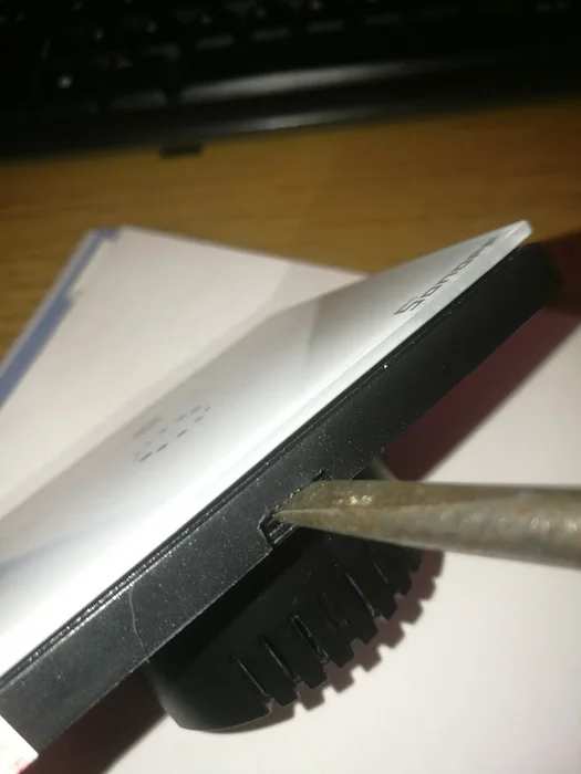
Simply insert a bladed screw driver into the tab as can be seen in the image above. Give the screw driver a twist and it will soon pop apart. Gentle though, don’t want to break the glass panel so early in the game.
Step 3: Removing the ESP Module Board
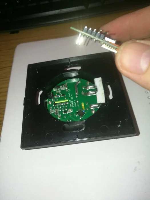
You can now remove the board we are interested in. It has a 2×2 header at the top of the board and a small double sided sticky pad at the bottom.
Carefully lift the board up using your screwdriver if need be, to work the board away for the sticky pad. Be gentle, we don’t want to break the board or bend the pins on the 2×2 header
Step 4: Modify the Board
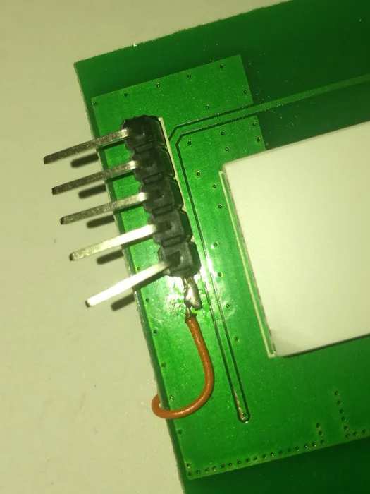
Now we need to break out the soldering iron.
While the iron is heating we need to prepare our 5 way header.
With a pair of long nose pliers, carefully push the 5th pin further down into the plastic header thereby lengthening the solder pin.
Once this is as long as can be, gently bend the lead out in line with the header plastic. You can see this better in the image above.
Now insert the 5 way header into the PCB and solder the 4 pins in place on the reverse of the board.
We now need to connect GPIO0 on the ESP8285 to the 5th pin of our header.
Using a magnifying glass and a steady hand, solder the short length of wire to GPIO0 as can be seen in the second image.
Once cooled, carefully dress the wire over the board and take it up to pin 5 of the header and again with your magnifying glass and a steady hand solder the wire on to pin 5.
You can apply a dab of superglue or hot melt glue to the wire to stop it wiggling around and breaking your solder joints.
Step 5: Hook It Up to Your FTDI/UNO
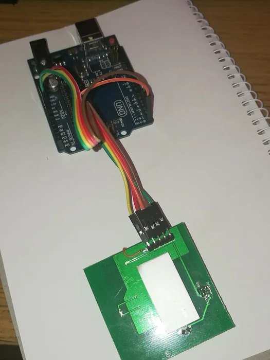
I use an UNO instead of an FTDI, only reason being there’s always one on my desk and its quicker to pop the MCU out and use that than hunt through my component drawers for an FTDI, yes I know lazy…
Any way we now need 5 Dupont wires, I’m using Female to Male
Header Colour Arduino
1 green GND
2 brown TX
3 orange RX
4 red 3.3V
5 yellow GND (This is the bent pin)
Check your connections over, paying attention to Pin 4, as this must only be connected to 3.3V, connecting to 5V will more than likely kill the ESP module.
Once you’re happy with the connections you can go ahead and hook up the USB lead.
Step 6: Run Some Tests
Start the Arduino editor and make sure it is connected to the correct serial port, if using the UNO it will be labelled along the lines of Port X (Arduino/Genuino Uno) where X is the actual port number.
Change the board to “Generic ESP8285 Module”
Download the Test_Sketch.ino file above, and save it to a folder called Test_Sketch
Open this in your Arduino IDE and Upload it to your touch plate.
Unplug Pin 5, this only needs to be connected while you are uploading your sketch
Open the Serial monitor.
Once you see the WiFi Led light on your touch plate, each time you touch the touch sensor it should light and you should see a message in the Serial Monitor indicating the touch sensor is activated.
If you are unable to upload the sketch try swapping pins 2 and 3, (TX/RX pins on the UNO or FTDI)
Step 7: The Last Sketch
Download the Live_sketch.ino above, save it to a folder Live_sketch
Load it into your Arduino IDE and edit the following lines..
Line 26:
const PROGMEM char* MQTT_CLIENT_ID = “Study Test Switch”;
Change “Study Test Switch” to something suitable for your installation.
Line 27:
const PROGMEM char* MQTT_USER = “MQTT User“;
Change “MQTT User” to the user name used to connect to you MQTT server and
Line 28:
const PROGMEM char* MQTT_PASSWORD = “MQTT Password”;
Change “MQTT Password” to your MQTT servers password
Lines 29 and 30:
const char* MQTT_LIGHT_STATE_TOPIC = “study/swtest/status”; const char*
const char* MQTT_LIGHT_COMMAND_TOPIC = “study/swtest/switch”;
Set the state and command topics inline with your naming conventions
Line 70:
WiFi.hostByName(“your_mgtt.server.co.uk”, MQTT_SERVER_IP);
Change “your_mqtt.server.co.uk” to the fully qualified domain name of your MQTT server.
Give your changes the once over to make sure they are correct then upload the sketch.
Step 8: Connect the Wall Plate to You WLan
After a couple of minutes open up your phones list of Wireless networks
Search for the network called “TaTaTatooouchMe” and join it.
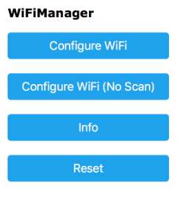
You will now be asked to authenticate which will produce a page as in the first image
Click ConfigureWiFi and You can now select your WLan, enter the passkey and click save.
After 10-15 seconds you device will be connected to you WLan
Check you device has reverted back to you WLan and the network “TaTaTatooouchMe” has disappeared
If not repeat the steps again
Step 9: Add the Touch Plate to Home Assistant
I separate all of my devices into separate files which I then include in the main configuration.yaml.
Please add this device to wherever you keep yours.
– platform: mqtt
name: “Main Light”
state_topic: “study/swtest/status”
command_topic: “study/swtest/switch”
payload_on: “ON”
payload_off: “OFF”
optimistic: false
You can alter the name to whatever you like, but you must make sure state_topic and command_topic match what you entered in the Live_sketch text on lines 29 and 30.
Run a test to make sure everything is ok with your new entry
/usr/local/bin/hass -c ./ –script check_config
If all appears ok restart hass
service hass-daemon restart
You should now see the new light switch in the home assistant gui.
Check you can toggle the switch from within Home assistant and vice-versa from the switch to home assistant.
Re-assemble your SONOFF and my work here is done.
Source: Hacking a Sonoff Touch Panel to Work With MQTT and Homeassistant
- What safety warnings are provided for this project?
The author warns that mains wiring can be dangerous and advises users not to hook up to mains themselves; additionally, UK devices may not comply with CE or UK safety laws. - Does the device require a neutral wire to work?
Yes, you will need a neutral for the devices to work as most UK light fittings only have live and the switch line. - How do you prepare the 5 way header for soldering?
You must push the 5th pin further down into the plastic header to lengthen it and then gently bend the lead out in line with the header plastic. - Which voltage must be connected to Pin 4 on the header?
Pin 4 must only be connected to 3.3V because connecting it to 5V will likely kill the ESP module. - What network name should you search for after uploading the sketch?
You should search for the wireless network called TaTaTatooouchMe to configure your WiFi settings. - How do you connect the wall plate to your home WLAN?
Join the TaTaTatooouchMe network, click ConfigureWiFi, select your WLAN, enter the passkey, and save to connect. - What steps are required to add the device to Home Assistant?
Add a platform mqtt entry with matching state_topic and command_topic names, check the configuration, and restart the hass daemon. - Can you swap pins if the upload fails?
Yes, if unable to upload the sketch, try swapping pins 2 and 3 which correspond to TX and RX pins.