This instructable is a guide for setting up an automated gardening system using an arduino and other cheap electronic parts. It allows sustainable gardening by using sensors to determine soil moisture, as well as a webscraper to determine future weather. It uses this information to save water by only using the requisite amount. Requirements for this project include experience soldering, some basic programming experience, and much patience for debugging.
Step 1: Build-Moisture Sensors
The moisture sensors rely on the resistivity of water to determine the moisture level of the soil. The sensors measure the resistance between two separate nails by sending a current through one of them and reading a corresponding voltage drop due to a known resistor value. The more water the lower the resistance, and using this we can determine threshold values for moisture content.
We will use three such sensors and use a multiplexor to alternate reading between them without using more than one arduino analog port.
While we will include a circuit board diagram, we recommend building the circuits on a breadboard first which will allow for both understanding and debugging.
Each sensor uses two nails, a 100 ohm resistor, and a 100 K-ohm resistor. We built a casing for each sensor with acrylic tubes, however this is not necessary.
Step 2: Build-Moisture Sensor- 1
The first step is to find two equal length nails of any type, although we found that longer and non-galvanized nails worked best (galvanized nails do not work at all). Next, a wire needs to be soldered to each nail. It is best to use weaved wire since it is flexible and less likely to break during use. The nails act as a heat sink, and to counteract this they must be heated before soldering. A hotplate was used to get the nails very hot.
A word of caution, as the name implies the hot plate gets extremely hot, as will the nails, so please use pliers to remove the nails from the hotplate.
It is useful to shrink wrap the soldered parts of the nails, especially if you are not planning to make a probe structure.
Step 3: Build-Moisture Sensor-2
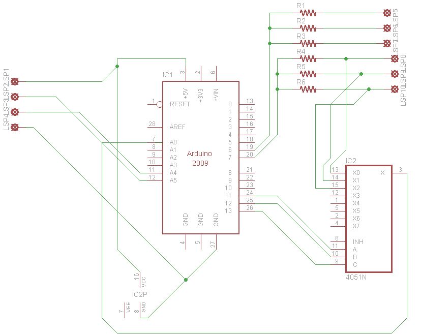
The next step is to wire the nails to the arduino. Use the circuit diagram provided. The sensor works by sending a fake AC current by alternating DC current between the two nails. The analog voltage is then read and a moisture level can be inferred. Our code for the whole project will be available. A picture of the finished sensor with acrylic covering is on the next page.
We read an input voltage into a multiplexor from a voltage dividor created by the 100K resistor. The 100 Ohm resistor, attached to the other lead of the sensor, is used for current limiting. Current limiting imposes an upper limit on the current coming into the arduino, which protects it from short-circuiting.
Step 4: Build-Moisture Sensor-3 (optional)
Take a hollow acrylic tube and attach it to a pointed front with two holes for nails. Seal the bottom from water with silicone glue. Make sure that the nails are not touching as this will short the circuit. Use a rubber stopper to seal the top. It is important that the nails be equal distances apart on each of the moisture sensors, as any variation could affect resistivity readings from one or more of the probes.
Step 5: Build-Moisture Sensor-4
To improve performance we used three soil moisture sensors. However, there may not be enough analog pins on the arduino to accommodate all of these depending on what other attachments you are using. We solved this problem by using a multiplexer, which allowed us to switch between and read from each of the three pairs of sensors. The circuit diagram is given below.
sensor
For more detail: Garduino-Automated Gardening System using Arduino


