Friction can often seem like a ‘boring’ force. Something we are all familiar with from a young age, but friction does a lot more than just make objects slow down – although that is a big part of this project. Friction allows the world to work as it is today. Friction between your shoes and the ground allows you to walk, friction between the bones in your joints allows you to finely operate things like your fingers, and a lot more.
In this Instructable, I will walk you through the most basic aspect of friction and how you can precisely calculate it, and – just saying – it is a lot more interesting than it sounds!
To give you a short rundown, there are two components to most basic calculations of friction, the coefficient of friction μ, and the normal force that the object exerts on its plane. Now, if what I just said sounds like utter jargon to you, don’t worry, I’ll explain all of this later on.
For this project, we are interested in calculating μ, and to do this we will use Infra-Red beams. I told you things were going to get interesting. With some fancy code – and the IR beams, we can accurately determine the speed of an object at the start and the end of its journey, much like a light gate – if you have done experiments involving them in physics class, and the speed information will allow us to get a somewhat accurate idea of the μ between the object and the surface it is on.
With this information, you can experiment with different surfaces, temperatures, humidity, and other control variables and play around with the intricate force that is friction.
Supplies
To build this project, you will:
- Some form of Microcontroller – however, this tutorial will be taught with the Arduino UNO
- Two sets of IR Break-Beam sensors – I found that Adafruit’s 3mm sensors work well
- 1 or more full-size bread-boards or multiple half-size breadboards
- Cardboard – Something to cut cardboard and glue/tape
- Some spare time
That’s pretty much it, but you can choose to jazz-up your creation with some buttons!
Step 1: THE ELECTRONICS SETUP PART 1
“Note that this part briefly explains how to electronics will be connected; this is not the final setup”
To begin with, let us cover the basics of the sensors we will be using; IR Bream-Beam Sensors. If you have watched one of those action-movie scenes in which people try very hard to touch laser beams that are placed around a room to guard a valuable possession, we will be building something similar, except on a smaller scale.
The way that these IR Sensors work is as follows:
There are two parts to these sets, the transmitter, and receiver. The transmitter – as the name suggests – transmits IR Radiation in a line. The receiver then scans for directed IR radiation, so when the beam released by the transmitter hits the sensor on the receiver module, the receiver returns a value of 1.
Conversely, when the beam from the transmitter is not pointed at the receiver or the beam is blocked by an object, the radiation does not reach the receiver and the module returns a value of 0.
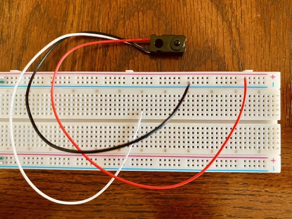
Wiring the transmitter is much like wiring an LED; one end needs to be connected to power, and the other to the ground, however, this time, we do not use any resistors, but before you power it, I recommend that you have a look at the product’s datasheet, as each manufacturer can have different standards, however for my Adafruit Sensors, resistors or capacitors are only optional.
IMAGE 1
Wiring the receiver is similar, two cables need to be wired to ground and power, and this time, the third cable carries the sensor’s signal – in other words, the sensor’s output data. In most sensors, this cable will be yellow or white, and the red and black cables will be for power and ground respectively; but just to make sure you don’t damage your sensor, take a quick look at your sensor’s datasheet. For now, attach the signal wire to an arbitrary spot on your breadboard, it can be connected to the Arduino later on.
IMAGE 2
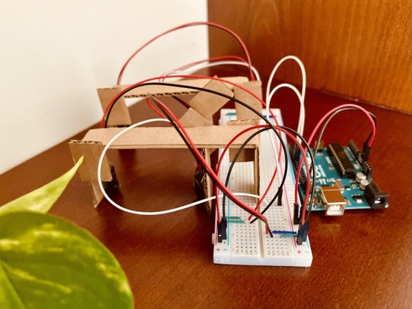
When all the connections have been made, it should look something like this: IMAGE 3 Alright, we have connected one of the sensors, let’s do the other! Follow the same wiring but on the other end of your breadboard/s. After you are done, it should look something like this! Just to keep things neat, I have changed up the layout of the sensors on the main build, but the wiring is essentially the same. If you are feeling confused about all of this, I recommend having a look at the following explanation of how breadboards work:
IMAGE 4
Step 2: THE PROGRAMMING – THE MAIN BIT
Throughout this section, refer to the lines of code on the first image of this step. I will describe the function of the program as the step progresses.
Tip: If at any point you feel stuck about the code, have a look at Arduino’s comprehensive documentation of code on their website, or drop me a comment, and I will try my best to reply!
As with most programs, this one begins by defining the important variables. On lines 2 and 3, I have defined the pins that I connected the two sensors to with the following lines of code:
#define sensor1Pin 7;<br>#define sensor2Pin 8;
Next, I define the state of each sensor with two variable variables on lines 6 and 7.
int sensorState1 = 0,
int sensorState2 = 0, <br>
On lines 10-14, I define 5 variables to count time:
int timeAccuracy = 20;
int timeCount1 = 0;
int timeInMS1 = 0;
int timeCount2 = 0;
int timeInMS2 = 0;<br>
Okay, those are all the variables – for now, so let me talk a bit about the main idea behind the code to make the next bits a lot easier to explain:
The main loop function in an Arduino program runs many thousands of times per second depending on load – far more accurate than this project is built for. To keep things manageable, many programs add a small time delay at the end of the loop function usualy ranging from 20-500 milliseconds. This time delay is the variable timeAccuracy.
The main idea is; that when an object blocks the first sensor while it is sliding across a surface, every loop of the loop() function will add 1 to the first timeCount. So say – an object blocks the sensor for one second with a 20-millisecond timeAccuracy delay, for 50 loops, the number 1 will be added to timeCount 1. As soon as the obejct passes the sensor, this process stops, and timeCount1 stops changing and is stable with a value of 50.
Now, by multiplying timeCount1 with timeAccuracy, we can get the time it took for the object to pass the sensor in milliseconds. 20*50 gives us 1000ms, or 1 second which – as we know – is the amount of time the object took to pass the sensor.
This same process is repeated with the second sensor, and so; by the end of these two processes, we now have the time the object took to pass both sensor 1 and sensor 2, and with a couple of quick and easy calculations, we can figure out the coefficient of kinetic friction between the object and the surface that the bject is resting on.
Phew! That took a while!
Now that the main strucutre of this step has been discussed, let me look at the main chunk of code:
To start off with; the setup() function. In this function, the code establishes a connection to Serial, for our results. The function also initializes digital pins senorPin1 and sensorPin2 as INPUT pins and turns on their pullups. For more information on the setting up of these sensors, have a look at Adafruit’s tutorial on using their sensors, which explains this setup part much better than I can:
void setup() {
  // set the mode of the sensor pins and turn on pullup:
  pinMode(sensor1Pin, INPUT);
  digitalWrite(sensor1Pin, HIGH);
  pinMode(sensor2Pin, INPUT);
  digitalWrite(sensor2Pin, HIGH);

  // establish a serial connection
  Serial.begin(9600);
}<br>
Now, before I dive into the loop() function, let me cover the two smaller functions I have written to count time, creatively named: time1 and time2.
Both are essentially the same function, just with different variables, so by explaining the first, I will end up explaining both:
The function comprises of two if statements: The first one checks if the sensor has been blocked, i.e. if it returns a value of 0, and if so, adds one to the respective timeCount variable. The second if statement checks if the sensor is open; i.e. that there is no object blocking it AND that the value for timeCount is greater than 0. What in essence, this if statement is doing, is running every time an object has crossed the sensor, not while it is crossing the sensor; after. Whatthis second does is multiplies the timeCount variable with timeAccuracy to gain timeInMS, and prints it out.
void time1() {
  // adds to timeCounter when the sensor's vision is blocked
  if (sensorState1 == 0) {
    timeCount1 = timeCount1 + 1; // have a go at optimizing this line!
  }
  // once the passage of the object is complete, calculate passed time and store it
  if (timeCount1 > 0 && sensorState1 == 1) {
    timeInMS1 = timeCount1 * timeAccuracy;
    Serial.println("1");
    Serial.println(timeInMS1);
    timeCount1 = 0;
  }
}

//
void time2() {
  // adds to timeCounter when the sensor's vision is blocked
  if (sensorState2 == 0) {
    timeCount2 = timeCount2 + 1; // have a go at optimizing this line!
  }
  // once the passage of the object is complete, calculate passed time and store it
  if (timeCount2 > 0 && sensorState2 == 1) {
    timeInMS2 = timeCount2 * timeAccuracy;
    Serial.println("2");
    Serial.print(timeInMS2);
    timeCount2 = 0;
  }
}<br>
Above is the code for those two functions.
Now that we have covered that, we move onto the last part of the first part of this coding summary, the loop() function.
This function is relatively simple, all it does is read the sensor1 and 2 pins and set the variables sensorState1 and sensorState2 to those values respectivly after which it calls the previous functions that I covered and bada-bing bada-boom, that’s it for now!
Wait, also, it calls a delay of length timeAccuracy at the end.
void loop(){
  // call counting functions etc
  sensorState1 = digitalRead(sensor1Pin);
  sensorState2 = digitalRead(sensor2Pin);

  time1();
  time2();

  delay(timeAccuracy);
Step 3: MAKE a CARBOARD THING
The way I plan to utilize these sensors is by arranging them in a straight line to detect when their beam gets broken. The problem with this is, however, that the sensors are quite loosey-goosey; they don’t stay in one place!
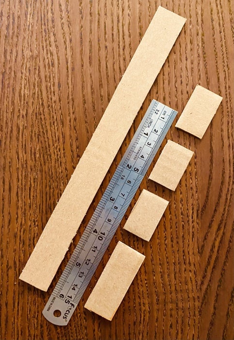
To do this, I will make two cardboard structures and they are made with some arbitrary measurements and depends heavily on your setup, but for scale, I have attached multiple images to the start of this step.
Realistically, all you need is a structure that can hold two sensors opposite each other.
Step 4: THE WIRING
Okay, so you’ve built your carboard thing, and everything is ready, including the first bit of code…
Time to put it all together and endure some fun, fun troubleshooting!
So we have already covered the basic wiring for the sensors, and this is no different, so instead of boring you with words – or at least a lot of words – have a good look at the photographs attached to this step and connect up your wires in a similar fashion.
If you are a bit stuck, read the following one-line descriptors of each image, and don’t hesitate to contact me through the comments, and I will get back to you as soon as I can.
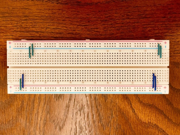
- Photo 1 is just about laying down the foundation that the sensors will be connected to.
- Photo 2 connects the two power rails together and connects the Arduino’s power pins to the breadboard
- Connect digital pins 7 and 8 to spots on your breadboard, these can be connected in the 5th step
- 3, slide the cardboard structures onto the middle-groove on your breadboard
- Finally, wire up the sensors and marvel at your creation!
Step 5: THE PROGRAMMING – THE CALCULATIONS
Let us add two more variables to our code:
int speed1 = 0;
int speed2 = 0;
These will, as expected, be the speeds of the object at the location of the two sensors. As we know, speed has two parts, distance and time. We can calculate the time, but to find the distance, let us create a variable called obejctLength that can be set manually. While we are on this, create a variable called normalForce and set that to the weight of your object, or in other words, the mass of you object – in grams – multiplied by 0.0098. For a more scientific explanation of this normal force, have a look at Khan Academy’s great video about it!
We will also need a couple more variables; objectMass, objectDecceleration, frictionForce, frictionCoefficient. Set the last three to 0, and the rest to the manual measurements that you conduct. For this sample, I am using a 9v Energizer battery, but use whatever you want!
#define objectLength 0.0265 // Meters
#define normalForce 0.0441 // Newtons
#define objectMass = 0.045 // Kilograms

int objectDeceleration = 0;
int frictionForce = 0;
int frictionCoeficcient = 0;
Note, that the length must be converted to meters, and the normalForce to kilograms.
We will also make some small changes to the time functions: see if you can spot the difference!
// first time counting function
  void time1() {
    // adds to timeCounter when the sensor's vision is blocked
    if (sensorState1 == 0) {
      timeCount1 = timeCount1 + 1; // have a go at optimizing this line!
    }
    // once the passage of the object is complete, calculate passed time and store it
    if (timeCount1 > 0 && sensorState1 == 1) {
      timeInMS1 = timeCount1 * timeAccuracy;
      speed1 = (objectLength/timeInMS1)/1000
      Serial.println("1");
      Serial.println(speed1);
      timeCount1 = 0;
    }
  }
Right after defining timeInMS1, I also define speed1 as the distance in meters divided by the time in milliseconds, but we need the time in seconds, so this entire calculation is divided by 1000.
Aaand, finally we need to create on small calculation function to take our readings and use them to calculate the coefficient of friction.
Now, this is the physics bit, so let me explain – in brief – the concepts behind the formulae before I dive into the code.
According to Newton’s Second law in motion, the Force Exerted on an object is EQUAL to the Mass of the object multiplied by the acceleration of the object. Friction, as a force, acts in the opposite direction to motion; so if you push an object forward, friction will act backwards, slowing down the object.
F = ma
In this equation, F is the frictional force, mass is the – well, mass, and a is the deceleration of our object DUE to friction.
We already know m, we set it as a variable earlier on, and we can calculate a. To do this, we assume that the deceleration is constant. We take the value for speed2 and take away speed1. The resulting calculation can be divided by approximately 0.2.
In-Depth – Newton’s Second Law
Now that we have the deceleration of our object, we can multiply the mass by the deceleration to get the frictional force.
Now, to calculate friction can also be calculated with the formula, F = Nμ. In this formula, F is the frictional force, N is the normal force and μ is the coefficient of friction.
We now know the frictional force, and the normal force, so finding the μ – coefficient of friction is going to be as easy as dividing the frictional force by the normal force.
The code is as follows:
void calculation() {
  objectDeceleration = (speed2-speed1)/0.2;
  frictionForce = objectMass * objectDeceleration;
  frictionCoefficient = frictionForce/normalForce;
  if (frictionCoefficient > 0) {
    Serial.println(frictionCoefficient);
  }
}
And that’s it, make sure to call calculation in the main loop and then you’re done. You’ve finished the programming, build the main structure, and now its ready to be deployed. Have a couple of test runs and tell me how they go!
Source: FRICTION CALCULATOR – WITH IR LASERS