Having made a lot of wearables as an engineer, advisor, and through replication, there’s one irritation that I find consistent with a lot of systems (mine included) – components (typically sensors & actuators) can’t be maneuvered to the wearer’s preferences. To begin to think about how to solve this issue, I’ve made this prototype system called Sensory Helping Hands. With the system, wearers are able to swap sensors/actuators/displays as well as orient the components wherever they want near their body (egocentric design). I also think this system would be an interesting way to prototype heads-up displays.
This system is the alpha of that idea, the benefit is that this project can be built with off-the-shelf parts for a reasonable price. The downside is that none of the mechanical parts are made for this purpose, so they can be difficult to integrate. However, I think the experience of wearing the Sensory Helping Hands is worth any difficulties, I think this one of the coolest things I’ve built and can’t wait to take it to the next level in the next iteration.
For future iterations, I want to design and 3D print a custom backplate that can support a high-resolution haptic display (8×8), custom connectors that can hold the sensors and actuators (currently I’m using cut acrylic and a lot of glue), an improved system for threading silicone wire through the arms, and more… If you’d like to help please feel free to reach out!
Special thanks to Michael Schneider for helping model, and to Will Harris for the valuable discussions while thinking through this system.
This project was developed in the Craft Tech Lab and ATLAS Institute at The University of Colorado, Boulder.
If you have any questions, want to keep up with my work, or just toss around ideas, please do so on my Twitter: @4Eyes6Senses. Thanks!
Step 1: Materials
Grove Shield FeatherWing for Particle Mesh and all Feathers
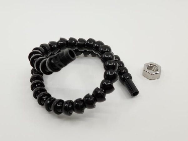
Helping hands soldering kit with flexible arms
4x Grove to STEMMA QT / Qwiic / JST SH Cable – 100mm long
4x A2 hex nuts (go to a hardware store and see what threads with your flexible arms – mine weren’t consistent)
4x Utility straps (I used these but they were low quality and would loosen easily)
4x small screws (2.5mm)
1x hard plastic sheet (I used acrylic)
Step 2: Make the Backplate
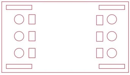
I used a laser cutter to make my backplate (used the “SensoryHelpingHands_Laser.pdf” file). However, it is possible to make the cutouts using a Dremel, the rectangles can vary in size but the holes need to be 13mm.
The current iteration of the backplate has 16 cutouts:
6x Circle holes for the flexible arms (13mm).
6x Rectangular holes to thread the cables from the flexible arms to the microcontroller.
4x Longer rectangular holes that are used for the straps.
Step 3: Attach Arms, Straps, and Shield
To attach the arms (Figure 1):
– Place the threaded end of the flexible arm through the circular hole in the backplate and then tighten the hex nut until the arm no longer wobbles or spins. If you are having trouble getting the nut tight enough, use a washer on the opposite side of the backplate. Repeat for the other three arms (Figure 3).
To attach the straps (Figure 2):
– thread the straps so that the clips will sit on the user’s chest when connected (Figure 4)
To attach the shield:
– Place shield on the center of the back piece. Using four small screws or hot glue, secure the shield to the backplate.
Step 4: How to Attach Sensors
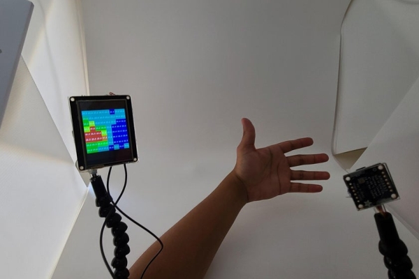
Currently, there’s no “perfect” way to attach sensors to the system. For the example (AMG8833 Thermal Camera Sensor and Adafruit 2.4 FTT FeatherWing display) this is what I did:
– Extend the Grove to STEMMA QT / Qwiic / JST SH Cable by cutting the middle of the cable and then soldering very thin silicone wire to one end (I used 30awg). I recommend adding heat shrink / electrical tape to each wire.
– Thread the wire through the flexible arm. This part can take some time, so do this step with patience in mind.
– Solder the other end of the cable to the silicone wire. I recommend adding heat shrink / electrical tape to each wire.
– Plug in the cable to the shield and the other end to the sensor. I used cut acrylic, cardboard, and hot glue to hold the display and sensor in place as there’s no custom attachments currently.
Step 5: Done!
You now have your very own Sensory Helping Hands! Enjoy!
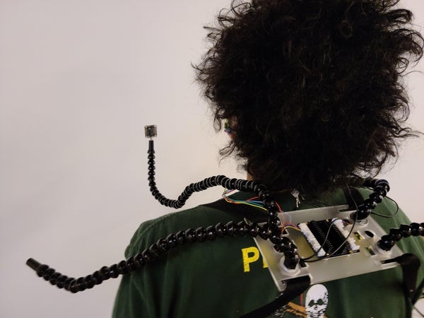
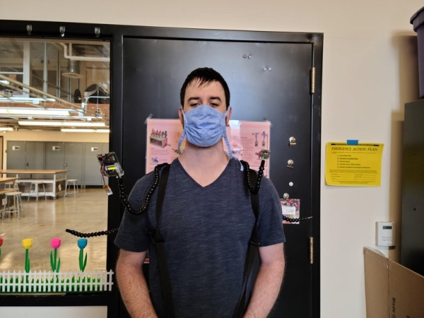
The above photos are my explorations around the Craft Tech Lab using the system with a thermal sensor and TFT display, and Michael showing the system on someone several inches taller than me. It was so much fun to explore with the system!
Source: Sensory Helping Hands: Modular Sensory Augmentation System (Prototype)